Asus Terminator A7VT400 Terminator A7VT400 User''s Manual for English - Page 59
using ribbon cables with pin 5 plug.
 |
View all Asus Terminator A7VT400 manuals
Add to My Manuals
Save this manual to your list of manuals |
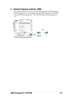
Page 59 highlights
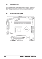
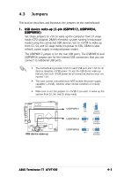
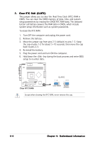
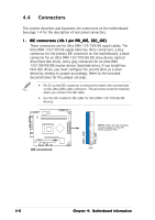
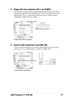
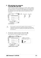
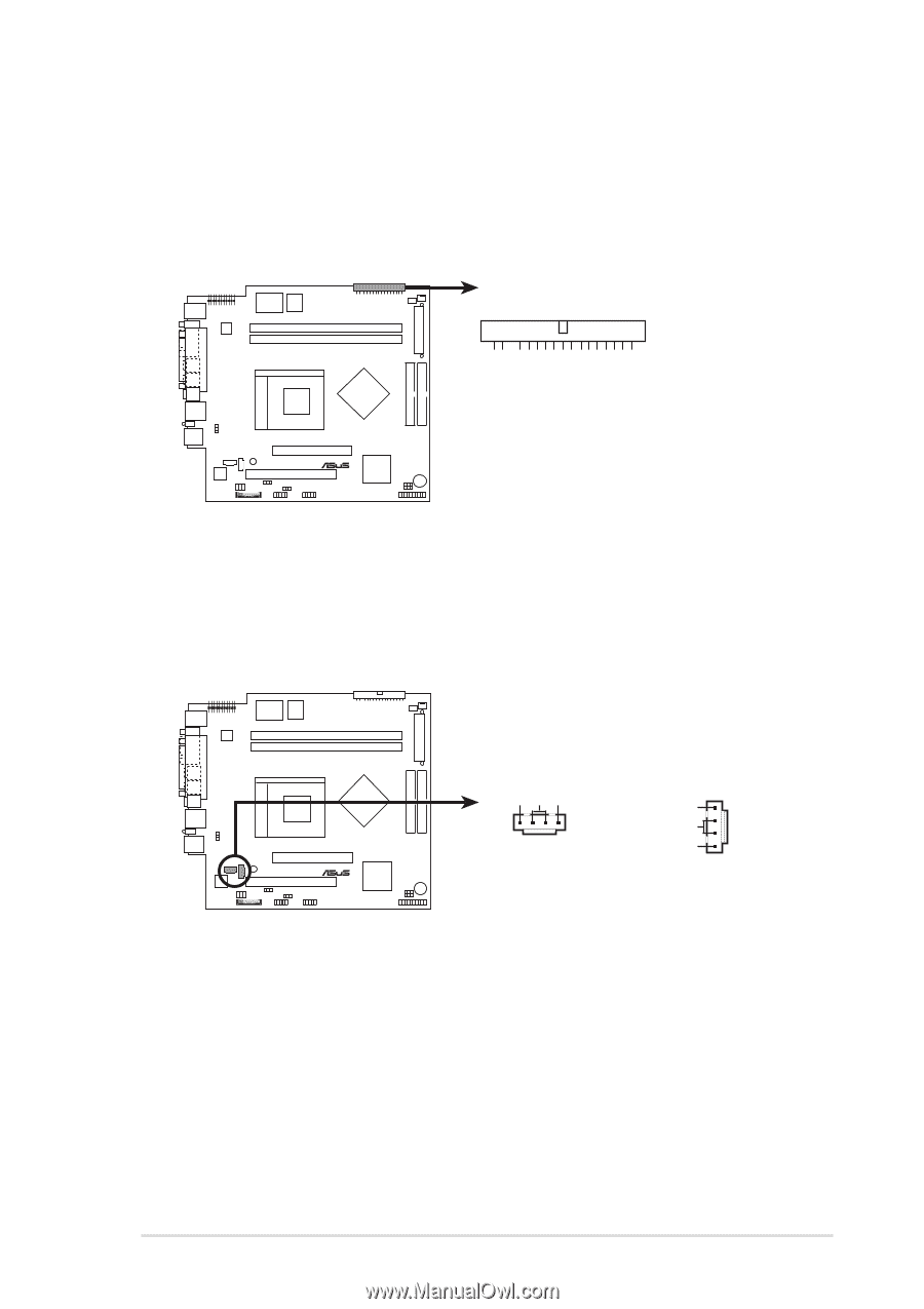
2 . Floppy disk drive connector (34-1 pin FLOPPY) This connector supports the provided floppy drive ribbon cable. After connecting one end to the motherboard, connect the other end to the floppy drive. (Pin 5 is removed to prevent incorrect insertion when using ribbon cables with pin 5 plug). FLOPPY NOTE: Orient the red markings on the floppy ribbon cable to PIN 1. ® Floppy disk drive connector 3 . Internal audio connectors (4-pin AUX, CD) These connectors allow you to receive stereo audio input from sound sources such as an optical drive, TV tuner, or MPEG card. Left Audio Channel Ground Right Audio Channel ® Internal audio connectors AUX (White) Right Audio Channel Ground CD (Black) Left Audio Channel ASUS Terminator T1 A7VT400 4-7
-
 1
1 -
2
-
3
-
4
-
5
-
6
-
7
-
8
-
9
-
10
-
11
-
12
-
13
-
14
-
15
-
16
-
17
-
18
-
19
-
20
-
21
-
22
-
23
-
24
-
25
-
26
-
27
-
28
-
29
-
30
-
31
-
32
-
33
-
34
-
35
-
36
-
37
-
38
-
39
-
40
-
41
-
42
-
43
-
44
-
45
-
46
-
47
-
48
-
49
-
50
-
51
-
52
-
53
-
 54
54 -
 55
55 -
 56
56 -
 57
57 -
 58
58 -
 59
59 -
 60
60 -
 61
61 -
 62
62 -
 63
63 -
 64
64 -
65
-
66
-
67
-
68
-
69
-
70
-
71
-
72
-
73
-
74
-
75
-
76
-
77
-
78
-
79
-
80
-
81
-
82
-
83
-
84
-
85
-
86
-
87
-
88
-
89
-
90
-
91
-
92
-
93
-
94
-
95
-
96
-
97
-
98
 |
 |
ASUS Terminator T1 A7VT400
ASUS Terminator T1 A7VT400
ASUS Terminator T1 A7VT400
ASUS Terminator T1 A7VT400
ASUS Terminator T1 A7VT400
4-7
4-7
4-7
4-7
4-7
2.
2.
2.
2.
2.
Floppy disk drive connector (34-1 pin FLOPPY)
Floppy disk drive connector (34-1 pin FLOPPY)
Floppy disk drive connector (34-1 pin FLOPPY)
Floppy disk drive connector (34-1 pin FLOPPY)
Floppy disk drive connector (34-1 pin FLOPPY)
This connector supports the provided floppy drive ribbon cable. After
connecting one end to the motherboard, connect the other end to the
floppy drive. (Pin 5 is removed to prevent incorrect insertion when
using ribbon cables with pin 5 plug).
3.
3.
3.
3.
3.
Internal audio connectors (4-pin AUX, CD)
Internal audio connectors (4-pin AUX, CD)
Internal audio connectors (4-pin AUX, CD)
Internal audio connectors (4-pin AUX, CD)
Internal audio connectors (4-pin AUX, CD)
These connectors allow you to receive stereo audio input from sound
sources such as an optical drive, TV tuner, or MPEG card.
fi
Floppy disk drive connector
FLOPPY
NOTE:
Orient the red markings on
the floppy ribbon cable to PIN 1.
fi
Internal audio connectors
AUX (White)
Right Audio Channel
Left Audio Channel
Ground
CD (Black)
Right Audio Channel
Left Audio Channel
Ground