Asus V2-PE3 V2-PE3 English Edition User's Manual
Asus V2-PE3 Manual
 |
View all Asus V2-PE3 manuals
Add to My Manuals
Save this manual to your list of manuals |
Asus V2-PE3 manual content summary:
- Asus V2-PE3 | V2-PE3 English Edition User's Manual - Page 1
Vintage V2-PE3 PC (Desktop Barebone) - Asus V2-PE3 | V2-PE3 English Edition User's Manual - Page 2
express written permission of ASUSTeK COMPUTER INC. ("ASUS"). Product warranty or service will not be extended if: (1) the ASUS HAS BEEN ADVISED OF THE POSSIBILITY OF SUCH DAMAGES ARISING FROM ANY DEFECT OR ERROR IN THIS MANUAL OR PRODUCT. SPECIFICATIONS AND INFORMATION CONTAINED IN THIS MANUAL - Asus V2-PE3 | V2-PE3 English Edition User's Manual - Page 3
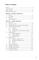
Table of contents Notices vi Safety information vi About this guide vii System package contents viii Chapter 1: System Introduction 1.1 Welcome 1-2 1.2 Front panel 1-2 1.3 Rear panel 1-4 1.4 Internal components 1-7 Chapter 2: Basic Installation 2.1 Preparation 2-2 2.2 Before you proceed - Asus V2-PE3 | V2-PE3 English Edition User's Manual - Page 4
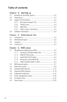
3-2 3.3.1 Running the support CD 3-3 3.3.2 Utilities menu 3-4 3.3.3 Make disk 3-5 3.3.4 ASUS contact information 3-5 3.4 Software information 3-6 Chapter 4: Motherboard Info 4.1 Introduction 4-2 4.2 Motherboard layout 4-2 4.3 Jumpers 4-3 4.4 Connectors 4-5 Chapter 5: BIOS setup 5.1 Managing - Asus V2-PE3 | V2-PE3 English Edition User's Manual - Page 5
. This equipment generates, uses and can radiate radio frequency energy and, if not installed and used in accordance with manufacturerʼs instructions, may cause harmful interference to radio communications. However, there is no guarantee that interference will not occur in a particular installation - Asus V2-PE3 | V2-PE3 English Edition User's Manual - Page 6
documentation that came with the package. • Before using the product, make sure all cables are correctly connected and the power cables are a stable surface. • If you encounter technical problems with the product, contact a qualified service technician or your retailer. Lithium-Ion Battery Warning - Asus V2-PE3 | V2-PE3 English Edition User's Manual - Page 7
About this guide Audience This guide provides general information and installation instructions about the ASUS Vintage V2-PE3 barebone system. This guide is intended for experienced users and integrators with hardware knowledge of personal computers. How this guide is organized This guide contains - Asus V2-PE3 | V2-PE3 English Edition User's Manual - Page 8
PE3 system package for the following items. If any of the items is damaged or missing, contact your retailer immediately. Item description 1. ASUS Vintage V2-PE3 barebone system with • ASUS motherboard • 300 W PFC power supply unit • ASUS chassis 2. Cable • AC power cable 3. Support CD 4. User guide - Asus V2-PE3 | V2-PE3 English Edition User's Manual - Page 9
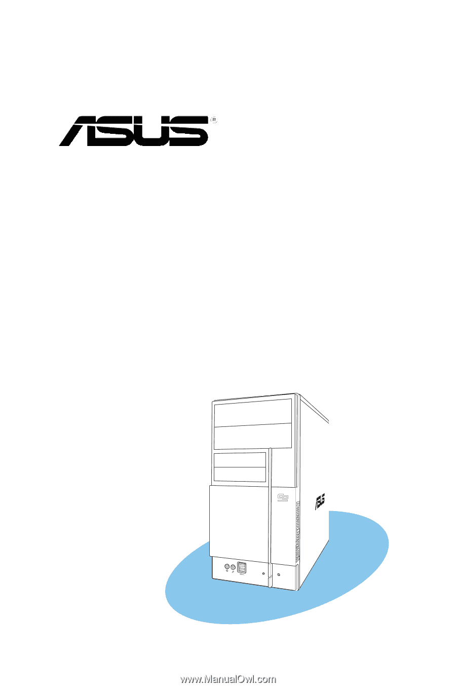
System introduction Chapter 1 This chapter gives a general description of the ASUS Vintage V2-PE3. The chapter lists the system features including introduction on the front and rear panel, and internal components. ASUS Vintage V2-PE3 - Asus V2-PE3 | V2-PE3 English Edition User's Manual - Page 10
Welcome! Thank you for choosing the ASUS Vintage V2-PE3! The ASUS Vintage V2-PE3 is an all-in-one barebone system with a versatile home entertainment feature. The system comes in a stylish mini-tower casing and powered by the ASUS motherboard that supports the Intel® Pentium® D, Intel® Pentium® 4 or - Asus V2-PE3 | V2-PE3 English Edition User's Manual - Page 11
, camera, PDA, and others. 7. Headphone port. This Line In (green) port connects a headphone with a stereo mini-plug. 8. Microphone port. This Mic (pink) port connects a microphone. ASUS Vintage V2-PE3 1-3 - Asus V2-PE3 | V2-PE3 English Edition User's Manual - Page 12
1.3 Rear panel The system rear panel includes the power connector and several I/O ports that allow convenient connection of devices. 1 2 12 3 4 5 6 13 7 1394 14 8 15 9 10 11 16 1. Power connector. This connector is for the power cable and plug. 2. Voltage selector. This switch allows - Asus V2-PE3 | V2-PE3 English Edition User's Manual - Page 13
Headset 2-s p e a k e r Line In Line Out Mic In 4-speaker Rear Speaker Out Front Speaker Out Mic In 6-speaker Rear Speaker Out Front Speaker Out Center/Subwoofer ASUS Vintage V2-PE3 1-5 - Asus V2-PE3 | V2-PE3 English Edition User's Manual - Page 14
Voltage selector The PSU has a 115 V/230 V voltage selector switch located beside the power connector. Use this switch to select the appropriate system input voltage according to the voltage supply in your area. If the voltage supply in your area is 100-127 V, set this switch to 115 V. If the - Asus V2-PE3 | V2-PE3 English Edition User's Manual - Page 15
BIOS FWP CLRTC1 F_PANEL FLOPPY 2 3 1 4 1. Front panel cover 2. 5.25-inch optical drive bays 3. Hard disk drive bay 4. Floppy disk drive bay 5. Power supply unit 6. CPU socket 7. DIMM sockets 8. ASUS motherboard 9. Chassis fan 10. AGP slot 11. PCI slots 12. Metal bracket lock ASUS Vintage V2-PE3 - Asus V2-PE3 | V2-PE3 English Edition User's Manual - Page 16
1-8 Chapter 1: System introduction - Asus V2-PE3 | V2-PE3 English Edition User's Manual - Page 17
Basic installation Chapter 2 This chapter provides step-by-step instructions on how to install components in the system. ASUS Vintage V2-PE3 - Asus V2-PE3 | V2-PE3 English Edition User's Manual - Page 18
came with the component. The motherboard comes with an onboard standby power LED. This LED lights up to indicate that the system is ON, in sleep mode or in soft-off mode, and not powered OFF. Unplug the power cable from the power outlet and make sure that the standby power LED - Asus V2-PE3 | V2-PE3 English Edition User's Manual - Page 19
hinge-like tabs on the right side of the assembly are exposed. 5. Remove the front panel assembly, then set aside. Air duct 3 1 2 3 1 3 2 Chassis tab holes 4 4 4 4 ASUS Vintage V2-PE3 2-3 - Asus V2-PE3 | V2-PE3 English Edition User's Manual - Page 20
instructions for the CPU, heatsink, and the retention mechanism. If the instructions in this section do not match the CPU documentation, follow the latter. • Check your motherboard to make the motherboard. ASUS will process Return Merchandise Authorization (RMA) requests only if the motherboard comes - Asus V2-PE3 | V2-PE3 English Edition User's Manual - Page 21
plate window to remove (4B). 4B 3 PnP cap Load plate 4A 5. Position the CPU over the socket, making sure that the gold triangle is on the bottom-left corner of the socket then fit the socket alignment key into the CPU notch. CPU notch Gold triangle mark Alignment key ASUS Vintage V2-PE3 2-5 - Asus V2-PE3 | V2-PE3 English Edition User's Manual - Page 22
Interface Material. If it gets into your eyes or touches your skin, make sure to wash it off immediately, and seek professional medical help. 7. Close the CPU fan and heatsink assembly. If you buy a CPU separately, make sure that you use only Intel®-certified multi-directional heatsink and fan. - Asus V2-PE3 | V2-PE3 English Edition User's Manual - Page 23
making sure that B the four fasteners match the holes on the motherboard. motherboard. CPU_FAN GND CPU FAN PWR CPU FAN IN CPU FAN PWM ® CPU FAN Connector Do not forget to connect the CPU fan connector! Hardware monitoring errors can occur if you fail to plug this connector. ASUS Vintage V2-PE3 - Asus V2-PE3 | V2-PE3 English Edition User's Manual - Page 24
misplacement in DDR DIMM sockets. The following figure illustrates the location of the sockets: ® DDR and DDR2 DIMM Sockets To prevent damage to the motherboard, do not use DDR and DDR2 memory simultaneously. 2.5.1 Memory configurations You may install 256 MB, 512 MB and 1 GB unbuffered non-ECC DDR - Asus V2-PE3 | V2-PE3 English Edition User's Manual - Page 25
W942508BH-5 VS32M8-5 PR1200528 N2DS25680BT-5T HY5DU56822AT-D43 HY5DU56822DT-D43 KDL684T4A2A-06 D3208DHIT-5 W942508BH-5 HY5DU56822BT-D43 MT46V32M8TG-5BC V58C2256804SCT5B K4H560838D-TCC4 K4H560838F-TCCC W942508BH-5 TMD7608F8E50D W942508BH-5 ASUS Vintage V2-PE3 2-9 - Asus V2-PE3 | V2-PE3 English Edition User's Manual - Page 26
DDR (400 MHz) Qualified Vendors List Size 256Mbytes 512Mbytes 512Mbytes 512Mbytes 512Mbytes 512Mbytes 512Mbytes 512Mbytes 512Mbytes 512Mbytes 512Mbytes 512Mbytes 512Mbytes 512Mbytes 512Mbytes 512Mbytes 512Mbytes 512Mbytes 512Mbytes 512Mbytes 512Mbytes 512Mbytes 512Mbytes 1024Mbytes Type Unbuffer - Asus V2-PE3 | V2-PE3 English Edition User's Manual - Page 27
. 2 1. Simultaneously press the retaining clips outward to unlock the DIMM. 1 1 DDR DIMM notch Support the DIMM lightly with your fingers when pressing the retaining clips. The DIMM might get damaged when it flips out with extra force. 2. Remove the DIMM from the socket. ASUS Vintage V2-PE3 2-11 - Asus V2-PE3 | V2-PE3 English Edition User's Manual - Page 28
support. Make sure to unplug the power cord before adding or removing expansion cards. Failure to do so may cause you physical injury and damage motherboard 1. Turn on the system and change the necessary BIOS settings, if any. See Chapter 5 for information on BIOS setup. 2. Assign an IRQ to the card. - Asus V2-PE3 | V2-PE3 English Edition User's Manual - Page 29
for ISA or PCI devices. IRQ assignments for this motherboard A B C D E F G H PCI drivers support "Share IRQ" or that the cards do not need IRQ assignments. Otherwise, conflicts will arise between the two PCI groups, making the system unstable and the card inoperable. ASUS Vintage V2-PE3 - Asus V2-PE3 | V2-PE3 English Edition User's Manual - Page 30
slot The Accelerated Graphics Port (AGP) slot supports AGP8X/4X cards. When you buy an AGP card, make sure that you ask for one with +1.5V specification. Note the notches on the card golden fingers to ensure that they fit the AGP slot on your motherboard. The below figure shows a graphic card to - Asus V2-PE3 | V2-PE3 English Edition User's Manual - Page 31
2.7 Installing an optical drive Refer to the instructions in this section if you wish to install a new optical drive. Follow these steps to install an optical drive: 1. , matching the red stripe on the cable with Pin 1 on the IDE interface. IDE ribbon cable Power cable ASUS Vintage V2-PE3 2-15 - Asus V2-PE3 | V2-PE3 English Edition User's Manual - Page 32
7. Connect the other end of the IDE ribbon cable to the secondary IDE connector (labeled SEC_IDE) on the motherboard. 8. Remove the dummy drive slot cover from the front panel. 9. Replace the front panel. 2-16 Chapter 2: Basic installation - Asus V2-PE3 | V2-PE3 English Edition User's Manual - Page 33
disk drive(s). To install a Serial ATA hard disk drive: 1. Place the chassis upright. 2. Use a screw driver to remove the HDD drive slot metal plate cover. 3. With the HDD label side up, carefully insert the drive . 4 4 3 4. Secure the drive with two screws on both sides. ASUS Vintage V2-PE3 2-17 - Asus V2-PE3 | V2-PE3 English Edition User's Manual - Page 34
the Serial ATA cable to the SATA connector at the back of the drive, then connect the other end to a Serial ATA connector on the motherboard. 6. Connect a 15-pin Serial ATA power plug from the power supply unit to the 15-pin power connector at the back of the drive. - OR - Asus V2-PE3 | V2-PE3 English Edition User's Manual - Page 35
primary IDE connector (blue connector labeled PRI_IDE) on the motherboard. IDE ribbon cable Power cable • If you will install only one hard disk drive, make sure to configure your hard disk drive as Master supply unit to the power connector at the back of the drive(s). ASUS Vintage V2-PE3 2-19 - Asus V2-PE3 | V2-PE3 English Edition User's Manual - Page 36
Vintage V2-PE3 system comes with one 3.25-inch drive bay for a floppy disk drive. To install a floppy disk drive: 1. Remove the front panel cover. For instructions of the signal cable to the floppy disk drive connector on the motherboard. See page 4-6 for the location of the floppy disk drive connector - Asus V2-PE3 | V2-PE3 English Edition User's Manual - Page 37
IDELED RESET Connect the reset button, power switch, power LED, and HDD LED cables to their respective leads in the system panel connector on the motherboard. See page 4-12 for the system panel descriptions. ASUS Vintage V2-PE3 2-21 - Asus V2-PE3 | V2-PE3 English Edition User's Manual - Page 38
bay cover locks. 2. Press the locks inward to release the bay cover. 3. Push the bay cover outward, then set it aside. 4. Follow the same instructions to remove the 3.5" drive bay cover. To reinstall the front panel assembly and side cover: 1. Insert the front panel assembly hinge-like tabs to the - Asus V2-PE3 | V2-PE3 English Edition User's Manual - Page 39
Chapter 3 This chapter helps you power up the system and install drivers and utilities from the support CD. ASUS Vintage V2-PE3 Starting up - Asus V2-PE3 | V2-PE3 English Edition User's Manual - Page 40
screen, press F6 when prompted then follow succeeding screen instructions to install the SATA drivers. 3.2 Powering up Press the system power button ( ) to enter the OS. Press to turn ON the system 3.3 Support CD information The support CD that came with the system contains useful software and - Asus V2-PE3 | V2-PE3 English Edition User's Manual - Page 41
driver Installs the S3G diaplay driver. Realtek ACʼ97 Audio Driver Installs the ACʼ97 audio driver. Realtek RTL8169/8110 Ethernet Driver Installs the Realtek RTL8169/8110 ethernet Driver. USB 2.0 Driver Installs the USB 2.0 driver file that came with the utility for details. ASUS Vintage V2-PE3 - Asus V2-PE3 | V2-PE3 English Edition User's Manual - Page 42
detected problems. This utility helps you keep your computer in healthy operating condition. ASUS Update The ASUS Update utility allows you to update the motherboard BIOS in a Windows® environment. This utility requires an Internet connection either through a network or an Internet Service Provider - Asus V2-PE3 | V2-PE3 English Edition User's Manual - Page 43
3.3.3 Make Disk VIA 32/64bit RAID Driver Creates the VIA 32/64bit RAID driver. 3.3.4 ASUS Contact information Click the Contact tab to display the ASUS contact information. You can also find this information on the inside front cover of this user guide. ASUS Vintage V2-PE3 3-5 - Asus V2-PE3 | V2-PE3 English Edition User's Manual - Page 44
in the support CD have wizards that will conveniently guide you through the installation. View the online help or readme file that came with the software for more information. ASUS PC Probe II PC Probe II is a utility that monitors the computerʼs vital components and alerts you of any problem with - Asus V2-PE3 | V2-PE3 English Edition User's Manual - Page 45
2. Click the Utilities tab, then click ASUS PC Probe II. 3. Follow the screen instructions to complete installation. Launching PC Probe II You can launch the PC Probe section by clicking on the triangle on the main window right handle. ASUS Vintage V2-PE3 Click to close the Preference panel 3-7 - Asus V2-PE3 | V2-PE3 English Edition User's Manual - Page 46
, memory, CPU usage window Shows/Hides the Preference section Minimizes the application Closes the application Sensor alert When a system sensor detects a problem, the main window right handle turns red, as the illustrations below show. When displayed, the monitor panel for that sensor also turns - Asus V2-PE3 | V2-PE3 English Edition User's Manual - Page 47
threshold values using the Config window. You cannot adjust the sensor threshold values in a small monitoring panel. Click to increase value Click to decrease value ASUS Vintage V2-PE3 3-9 - Asus V2-PE3 | V2-PE3 English Edition User's Manual - Page 48
Monitoring sensor alert The monitor panel turns red when a component value exceeds or is lower than the threshold value. Refer to the illustrations below. Small display Large display WMI browser Click to display the WMI (Windows Management Instrumentation) browser. This browser displays - Asus V2-PE3 | V2-PE3 English Edition User's Manual - Page 49
display the information on the right panel. The pie chart at the bottom of the window represents the used (blue) and the available HDD space. ASUS Vintage V2-PE3 3-11 - Asus V2-PE3 | V2-PE3 English Edition User's Manual - Page 50
Memory usage The Memory tab shows both used and available physical memory. The pie chart at the bottom of the window represents the used (blue) and the available physical memory. Configuring PC Probe II Click to view and adjust the sensor threshold values. The Config window has two tabs: Sensor/ - Asus V2-PE3 | V2-PE3 English Edition User's Manual - Page 51
Motherboard info Chapter 4 This chapter gives information about the motherboard that comes with the system. This chapter includes the motherboard layout, jumper settings, and connector locations. ASUS Vintage V2-PE3 - Asus V2-PE3 | V2-PE3 English Edition User's Manual - Page 52
Vintage V2-PE3 barebone system comes with an ASUS motherboard. This chapter provides technical information about the motherboard for future upgrades or system reconfiguration. 4.2 Motherboard VIA VT8237R Plus SATA1 IR_CON USB78 4Mb BIOS FWP CLRTC1 F_PANEL FLOPPY 4-2 Chapter 4: Motherboard info - Asus V2-PE3 | V2-PE3 English Edition User's Manual - Page 53
key during the boot process and enter BIOS setup to re-enter data. ® Clear RTC RAM CLRTC 2 1 Normal (Default) 3 2 Clear CMOS Except when clearing the RTC RAM, never remove the cap on CLRTC jumper default position. Removing the cap will cause system boot failure. ASUS Vintage V2-PE3 4-3 - Asus V2-PE3 | V2-PE3 English Edition User's Manual - Page 54
the jumper cap. ® . BIOS_WP FWP WRITE ENABLE WRITE PROTECT (Default) A warning message "Please make sure whether lockout jumper is set to correct or not." appears when you flash the BIOS with the jumper cap. Remove the jumper cap before you update your BIOS. 4-4 Chapter 4: Motherboard info - Asus V2-PE3 | V2-PE3 English Edition User's Manual - Page 55
notes on Serial ATA: • You must install Windows® 2000 Service Pack 4 or the Windows® XP Service Pack1 before using Serial ATA hard disk drives. • When using the connectors in Standard IDE mode, connect the primary (boot) hard disk drive to the SATA1 or SATA2 connector. ASUS Vintage V2-PE3 4-5 - Asus V2-PE3 | V2-PE3 English Edition User's Manual - Page 56
/66 signal cable: blue, black, and gray. Connect the blue connector to the motherboardʼs IDE connector, then select one of the following modes to configure your device device jumper is set as "Cable-Select", make sure all other device jumpers have the same setting. 4-6 Chapter 4: Motherboard info - Asus V2-PE3 | V2-PE3 English Edition User's Manual - Page 57
support cooling fans of 350 mA~740 mA (8.88 W max.) or a total of 1 A~2.22 A (26.64 W max.) at +12V. Connect the fan cables to the fan connectors on the motherboard, making the USB connectors. Doing so will damage the motherboard! The USB module is purchased separately. ASUS Vintage V2-PE3 4-7 - Asus V2-PE3 | V2-PE3 English Edition User's Manual - Page 58
inadequate. • The power suppply unit (PSU) available along with this barebone system has a 24-pin plug. Match the 1-20 pins of this plug to the ATX power connector and leave the 21-24 pins idle. • Make sure that your power supply unit (PSU) can provide at least the minimum 4: Motherboard info - Asus V2-PE3 | V2-PE3 English Edition User's Manual - Page 59
connector is for a chassis-mounted front panel audio I/O module that supports legacy ACʼ97 audio standard. ® FP_AUDIO Front Panel Audio Connector panel audio module to this connector to avail of the motherboardʼs high-definition audio capability. 9. Digital audio connector GND ASUS Vintage V2-PE3 4-9 - Asus V2-PE3 | V2-PE3 English Edition User's Manual - Page 60
the back of the system chassis. (optional) ® IE1394_1 1 IEEE 1394 Connector Never connect a USB cable to the IEEE 1394 connector. Doing so will damage the motherboard! TPA2GND TPB2+12V GND TPA2+ GND TPB2+ +12V 4-10 Chapter - Asus V2-PE3 | V2-PE3 English Edition User's Manual - Page 61
Module connector (5-1 pin IR_CON) This connector supports a wireless transmitting and receiving infrared module. The module on this motherboard, set the item UART Mode Select to [IrDA] or [ASKIR] in the BIOS. Refer to "5.5 Integrated Peripherals" on page 5-14 for details. ASUS Vintage V2-PE3 4-11 - Asus V2-PE3 | V2-PE3 English Edition User's Manual - Page 62
System panel connector (10-1 pin PANEL) This connector supports several chassis-mounted functions. PWRLED PWRSW PWR_LED+ PWR_LEDPWR the system ON or puts the system in SLEEP or SOFT-OFF mode depending on the BIOS settings. Pressing the power switch for more than four seconds while the system is ON - Asus V2-PE3 | V2-PE3 English Edition User's Manual - Page 63
Chapter 5 This chapter tells how to change system settings through the BIOS Setup menus and describes the BIOS parameters. BIOS setup ASUS Vintage V2-PE3 1 - Asus V2-PE3 | V2-PE3 English Edition User's Manual - Page 64
3. ASUS CrashFree BIOS 2 (Updates the BIOS using a bootable floppy disk or the motherboard support CD when the BIOS file fails or gets corrupted.) Refer to the corresponding sections for details on these utilities. Save a copy of the original motherboard BIOS file to a bootable floppy disk in case you - Asus V2-PE3 | V2-PE3 English Edition User's Manual - Page 65
. Follow these instructions to update the BIOS using this utility. 1. Download the latest BIOS file from the ASUS web site. Rename the file to P5VDCTVM.BIN and save it to a floppy disk. Save only the updated BIOS file in the floppy disk to avoid loading the wrong BIOS file. ASUS Vintage V2-PE3 5-3 - Asus V2-PE3 | V2-PE3 English Edition User's Manual - Page 66
off or reset the system during the flashing process! Message: Do You Want To Save Bios (Y/N) AwardBIOS Flash Utility for ASUS V1.14 (C) Phoenix Technologies Ltd. All Rights Reserved For P4M800-8237R-P5VDC-TVM-00 DATE:05/01/2006 Flash Type - PMC Pm49FL004T LPC/FWH File Name to Program: p5vdctvm - Asus V2-PE3 | V2-PE3 English Edition User's Manual - Page 67
Phoenix Technologies Ltd. All Rights Reserved floppy disk, then returns For P4M800-8237R-P5VDC-TVM-00 DATE:05/01/2006 to the BIOS flashing Flash Type - PMC Pm49FL004T LPC/FWH process. File Name to Program: 01.bin Now Backup System BIOS to File! Message: Please Wait! ASUS Vintage V2-PE3 5-5 - Asus V2-PE3 | V2-PE3 English Edition User's Manual - Page 68
process. You can update a corrupted BIOS file using the motherboard support CD or the floppy disk that contains the updated BIOS file. • Prepare the motherboard support CD or the floppy disk containing the updated motherboard BIOS before using this utility. • Make sure that you rename the original or - Asus V2-PE3 | V2-PE3 English Edition User's Manual - Page 69
BIOS menu screen. See section "2.2 BIOS menu screen." • The BIOS setup screens shown in this section are for reference purposes only, and may not exactly match what you see on your screen. • Visit the system builderʼs website to download the latest BIOS file for this motherboard. ASUS Vintage V2-PE3 - Asus V2-PE3 | V2-PE3 English Edition User's Manual - Page 70
menu screen When you enter the BIOS, the following screen appears. The BIOS menu screen displays the items that allow you to make changes to the system configuration. To access the menu items, press the up/down/right/left arrow key on the keyboard until the desired - Asus V2-PE3 | V2-PE3 English Edition User's Manual - Page 71
and their corresponding functions. Practice navigating through the various menus and sub-menus. If you accidentally make unwanted changes to any of the fields, press to load the fail-safe default . This window displays the help text for the currently highlighted field. ASUS Vintage V2-PE3 5-9 - Asus V2-PE3 | V2-PE3 English Edition User's Manual - Page 72
CMOS Setup Utility Standard BIOS Features Date (mm:dd:yy) Time (hh:mm:ss) IDE Channel 0 Master IDE Channel 0 Slave IDE Channel 1 Master IDE Channel 1 Slave SATA Channel 2 Master SATA Channel 3 Master Mon, Jan 24 2005 11 : 35 : 24 [ST320410A] [ASUS CD-S520/A] [None] [None] [None] [None] Select - Asus V2-PE3 | V2-PE3 English Edition User's Manual - Page 73
disk drive information into the BIOS, use a disk utility, such as FDISK, to partition and format new IDE hard disk drives. This is necessary so that you can write or read data from the hard disk. Make sure to set the partition of the Primary IDE hard disk drives to active. ASUS Vintage V2-PE3 5-11 - Asus V2-PE3 | V2-PE3 English Edition User's Manual - Page 74
to display the SATA device information. Phoenix - Award BIOS CMOS Setup Utility SATA Channel 2 Master IDE Auto-Detection Extended IDE Large] [Auto] Before attempting to configure a hard disk drive, make sure you have the correct configuration information supplied by the drive manufacturer - Asus V2-PE3 | V2-PE3 English Edition User's Manual - Page 75
configurable. After entering the IDE hard disk drive information into the BIOS, use a disk utility, such as FDISK, to partition and format so that you can write or read data from the hard disk. Make sure to set the partition of the Primary IDE hard disk drives to Disk/Key] ASUS Vintage V2-PE3 5-13 - Asus V2-PE3 | V2-PE3 English Edition User's Manual - Page 76
. Incorrect field values may cause the system to malfunction. Phoenix - Award BIOS CMOS Setup Utility Advanced BIOS Features CPU Feature Hard Disk Boot Priority First Boot Device Second Boot Device Third screen depends on the number of devices installed in the system. 5-14 Chapter 5: BIOS setup - Asus V2-PE3 | V2-PE3 English Edition User's Manual - Page 77
password before entering the BIOS Setup. Select [System] to require the password before entering the system. Configuration options: [Setup] [System] Full Screen LOGO Show [Enabled] Enable or disable full screen logo show support.Configuration options: [Enabled] [disabled] ASUS Vintage V2-PE3 5-15 - Asus V2-PE3 | V2-PE3 English Edition User's Manual - Page 78
Defaults Onchip IDE Device This sub-menu contains IDE function-related items. Select an item then press to edit. Select Menu Phoenix - Award BIOS CMOS Setup Utility Item Specific Help Onchip IDE Device IDE Primary Master PIO IDE Primary Slave PIO IDE Secondary Master PIO IDE Secondary Slave - Asus V2-PE3 | V2-PE3 English Edition User's Manual - Page 79
Allows you to enable or disable USB mouse support. Configuration options: [Disabled] [Enabled] AC97 Audio [Auto] Allows the BIOS to automatically enable support for legacy AC`97 audio, or disable the onboard AC`97 Audio controller. Configuration options: [Enabled] [Disabled] ASUS Vintage V2-PE3 5-17 - Asus V2-PE3 | V2-PE3 English Edition User's Manual - Page 80
] Allows you to enable or disable the onboard LAN device support. Configuration options: [Disabled] [Enabled] Onboard LAN Boot SuperIO devices. Select an item then press to edit. Phoenix - Award BIOS CMOS Setup Utility SuperIO Device Onboard Serial Port 1 Onboard Serial POrt 2 UART Mode - Asus V2-PE3 | V2-PE3 English Edition User's Manual - Page 81
is used to control serial devices. Select [IrDA] or [ASKIR] if you connect any infrared devices to the motherboard. IrDA provides a max speed of up to 115K baud while ASKIR reaches a max speed of 19.2K baud Mode is set to [ECP] or [ECP+EPP]. Configuration options: [1] [3] ASUS Vintage V2-PE3 5-19 - Asus V2-PE3 | V2-PE3 English Edition User's Manual - Page 82
Advanced Configuration and Power Interface (ACPI). Phoenix - Award BIOS CMOS Setup Utility Power Management Setup ACPI Function ACPI Suspend Type Defaults ACPI Function [Enabled] Allows you to enable or disable the ACPI support for the operating system. Configuration options: [Enabled] [Disabled] - Asus V2-PE3 | V2-PE3 English Edition User's Manual - Page 83
loss. When set to Former-Sts, the system goes to its previous state before the AC power loss. Configuration options: [Off] [On] [Former-Sts] ASUS Vintage V2-PE3 5-21 - Asus V2-PE3 | V2-PE3 English Edition User's Manual - Page 84
5.8 PC Health Status The PC Health Status screen shows the motherboard CPU and fan temperatures, and allows you to set threshold levels for efficient system operation. Phoenix - Award BIOS CMOS Setup Utility PC Health Status CPU Temperature MB Temperature CPU Fan Speed System Fan Speed VCORE - Asus V2-PE3 | V2-PE3 English Edition User's Manual - Page 85
to set a user password for access to system after boot-up. Save & Exit Setup Once you are finished making your selections, choose this option to ensure that the values you selected are saved to the CMOS RAM. When you to save the changes that you made to the Setup program. ASUS Vintage V2-PE3 5-23
-
 1
1 -
 2
2 -
 3
3 -
 4
4 -
 5
5 -
 6
6 -
 7
7 -
8
-
9
-
10
-
11
-
12
-
13
-
14
-
15
-
16
-
17
-
18
-
19
-
20
-
21
-
22
-
23
-
24
-
25
-
26
-
27
-
28
-
29
-
30
-
31
-
32
-
33
-
34
-
35
-
36
-
37
-
38
-
39
-
40
-
41
-
42
-
43
-
44
-
45
-
46
-
47
-
48
-
49
-
50
-
51
-
52
-
53
-
54
-
55
-
56
-
57
-
58
-
59
-
60
-
61
-
62
-
63
-
64
-
65
-
66
-
67
-
68
-
69
-
70
-
71
-
72
-
73
-
74
-
75
-
76
-
77
-
78
-
79
-
80
-
81
-
82
-
83
-
84
-
85
 |
 |
Vintage V2-PE3
PC (Desktop Barebone)