Asus V2-PE3 V2-PE3 English Edition User's Manual - Page 60
COM Port Connector, IEEE 1394 Connector
 |
View all Asus V2-PE3 manuals
Add to My Manuals
Save this manual to your list of manuals |
Page 60 highlights
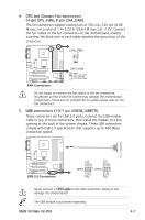
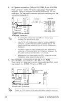
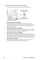
10. Serial port connector (10-1 pin COM2) This connector is for a serial (COM) port. Connect the serial port module cable to this connector, then install the module to a slot opening at the back of the system chassis. COM2 PIN 1 ® COM Port Connector 11 IEEE 1394 port (10-1 pin IE1394_1) This connector is for a IEEE 1394 port. Connect the IEEE 1394 module cable to this connector, then install the module to a slot opening at the back of the system chassis. (optional) ® IE1394_1 1 IEEE 1394 Connector Never connect a USB cable to the IEEE 1394 connector. Doing so will damage the motherboard! TPA2GND TPB2+12V GND TPA2+ GND TPB2+ +12V 4-10 Chapter 4: Motherboard info
-
 1
1 -
2
-
3
-
4
-
5
-
6
-
7
-
8
-
9
-
10
-
11
-
12
-
13
-
14
-
15
-
16
-
17
-
18
-
19
-
20
-
21
-
22
-
23
-
24
-
25
-
26
-
27
-
28
-
29
-
30
-
31
-
32
-
33
-
34
-
35
-
36
-
37
-
38
-
39
-
40
-
41
-
42
-
43
-
44
-
45
-
46
-
47
-
48
-
49
-
50
-
51
-
52
-
53
-
54
-
 55
55 -
 56
56 -
 57
57 -
 58
58 -
 59
59 -
 60
60 -
 61
61 -
 62
62 -
 63
63 -
 64
64 -
 65
65 -
66
-
67
-
68
-
69
-
70
-
71
-
72
-
73
-
74
-
75
-
76
-
77
-
78
-
79
-
80
-
81
-
82
-
83
-
84
-
85
 |
 |
4-10
Chapter 4: Motherboard info
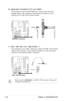
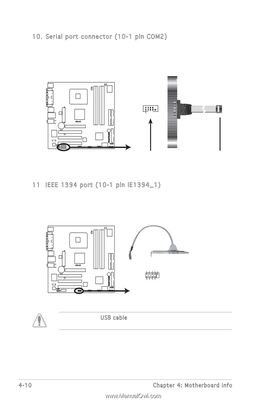
10. Serial port connector (10-1 pin COM2)
This connector is for a serial (COM) port. Connect the serial port
module cable to this connector, then install the module to a slot
opening at the back of the system chassis.
COM Port Connector
PIN 1
COM2
11 IEEE 1394 port (10-1 pin IE1394_1)
This connector is for a IEEE 1394 port. Connect the IEEE 1394 module
cable to this connector, then install the module to a slot opening at
the back of the system chassis.
(optional)
IEEE 1394 Connector
IE1394_1
TPA2-
GND
TPB2-
+12V
GND
TPA2+
GND
+12V
1
TPB2+
Never connect a
USB
cable to the IEEE 1394 connector. Doing so will
damage the motherboard!