Asus V2-PE3 V2-PE3 English Edition User's Manual - Page 58
ATX Power Connectors, Internal Audio Connectors
 |
View all Asus V2-PE3 manuals
Add to My Manuals
Save this manual to your list of manuals |
Page 58 highlights
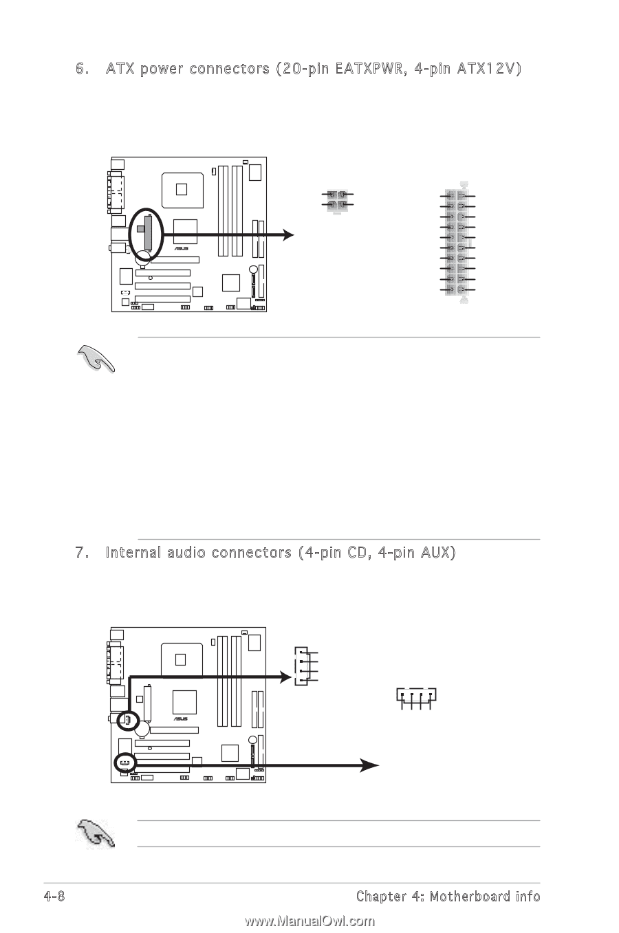
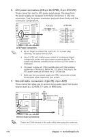
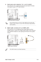
6. ATX power connectors (20-pin EATXPWR, 4-pin ATX12V) These connectors are for ATX power supply plugs. The plugs from the power supply are designed to fit these connectors in only one orientation. Find the proper orientation and push down firmly until the connectors completely fit. ATX12V ATXPWR GND +12V DC GND +12.0VDC +12V DC +5VSB +5.0VDC +5.0VDC PWR_OK -5.0VDC GND GND +5.0VDC GND ® GND GND +5.0VDC PS_ON# GND GND +3.3VDC -12.0VDC +3.3VDC +3.3VDC ATX Power Connectors • Do not forget to connect the 4-pin ATX +12 V power plug; otherwise, the system will not boot. • Use of a PSU with a higher power output is recommended when configuring a system with more power-consuming devices. The system may become unstable or may not boot up if the power is inadequate. • The power suppply unit (PSU) available along with this barebone system has a 24-pin plug. Match the 1-20 pins of this plug to the ATX power connector and leave the 21-24 pins idle. • Make sure that your power supply unit (PSU) can provide at least the minimum power required by your system. 7. Internal audio connectors (4-pin CD, 4-pin AUX) These connectors allow you to receive stereo audio input from sound sources such as a CD-ROM, TV tuner, or MPEG card. CD (black) Right Audio Channel Ground Ground Left Audio Channel AUX (white) ® Left Audio Channel Ground Ground Right Audio Channel Internal Audio Connectors Enable the CD-IN function in the audio utility when using this connector. 4-8 Chapter 4: Motherboard info
-
 1
1 -
2
-
3
-
4
-
5
-
6
-
7
-
8
-
9
-
10
-
11
-
12
-
13
-
14
-
15
-
16
-
17
-
18
-
19
-
20
-
21
-
22
-
23
-
24
-
25
-
26
-
27
-
28
-
29
-
30
-
31
-
32
-
33
-
34
-
35
-
36
-
37
-
38
-
39
-
40
-
41
-
42
-
43
-
44
-
45
-
46
-
47
-
48
-
49
-
50
-
51
-
52
-
 53
53 -
 54
54 -
 55
55 -
 56
56 -
 57
57 -
 58
58 -
 59
59 -
 60
60 -
 61
61 -
 62
62 -
 63
63 -
64
-
65
-
66
-
67
-
68
-
69
-
70
-
71
-
72
-
73
-
74
-
75
-
76
-
77
-
78
-
79
-
80
-
81
-
82
-
83
-
84
-
85
 |
 |