Asus V2-PE3 V2-PE3 English Edition User's Manual - Page 15
Internal components - pe3 bios
 |
View all Asus V2-PE3 manuals
Add to My Manuals
Save this manual to your list of manuals |
Page 15 highlights
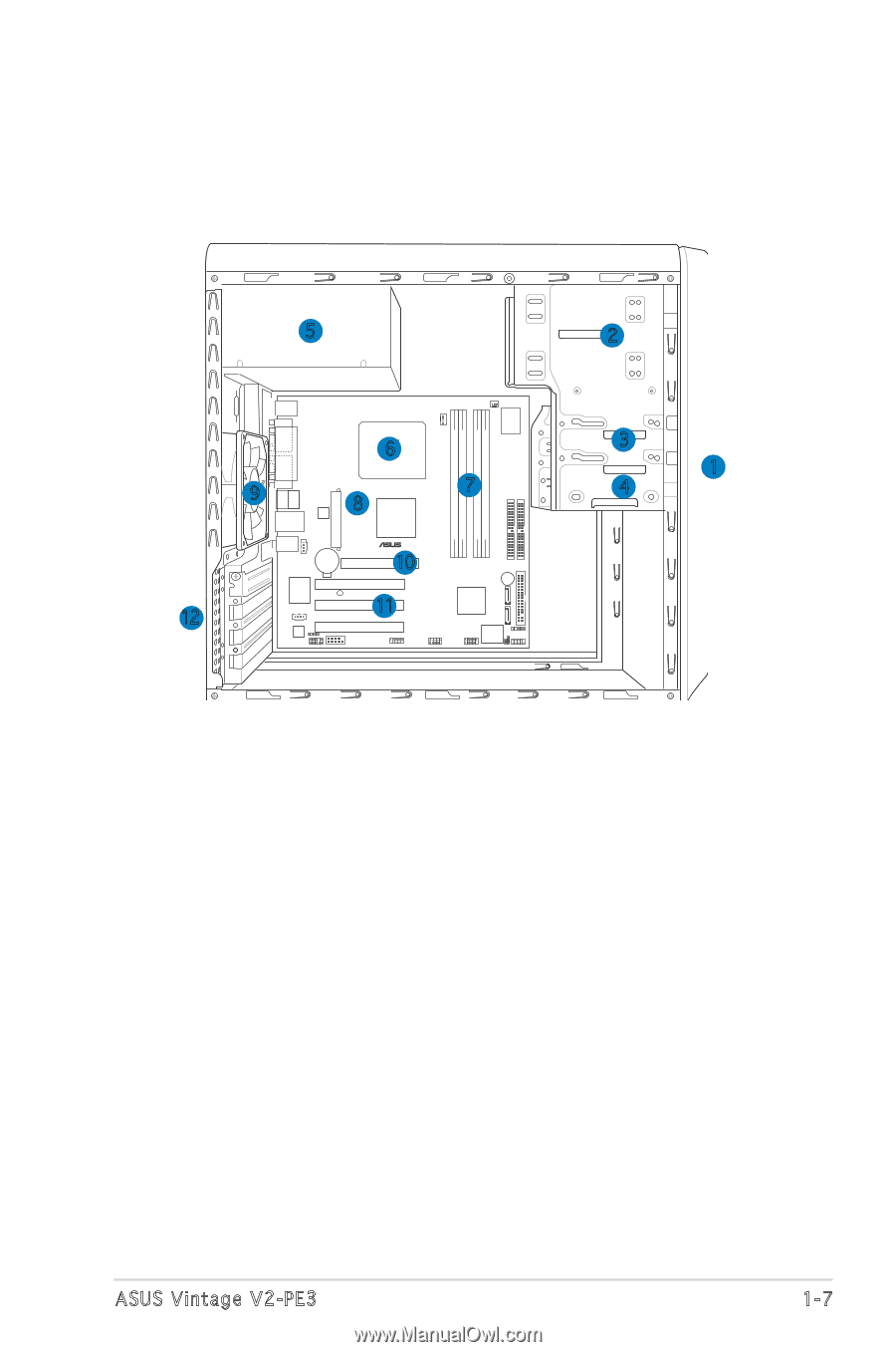
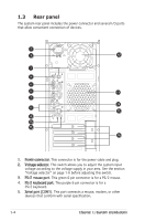
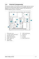
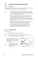
1.4 Internal components The illustration below is the internal view of the system when you remove the top cover and the power supply unit. The installed components are labeled for your reference. Proceed to Chapter 2 for instructions on installing additional system components. 5 12 PS/2KBMS T: Mouse B: Keyboard COM1 CPU_FAN LGA775 6 CHA_FAN Super I/O DDR2 DIMM_A1 (128 bit,240-pin module) DDR2 DIMM_B1 (128 bit,240-pin module) DDR DIMM_A1 (64 bit,184-pin module) DDR DIMM_B1 (64 bit,184-pin module) PRI_IDE SEC_IDE PARALLEL PORT ATXPWR 9 VGA BOTTOM: TOP: USB1 IE1394 USB2 ATX12V LAN_USB34 8 VIA P4M800 PRO Top:Rear Speaker Out CD Center: Side Speaker Out Below: Center/Subwoofer CR2032 3V Lithium Cell CMOS Power ® 10 AGP RTL8100S AUX PCI1 SB_PWR PCI2 11 SPDIF_OUT ALC655 FP_AUDIO COM1 PCI3 IE1394_1 USB56 7 BUZZER VIA VT837R Plus SATA2 SATA1 IR_CON USB78 4Mb BIOS FWP CLRTC1 F_PANEL FLOPPY 2 3 1 4 1. Front panel cover 2. 5.25-inch optical drive bays 3. Hard disk drive bay 4. Floppy disk drive bay 5. Power supply unit 6. CPU socket 7. DIMM sockets 8. ASUS motherboard 9. Chassis fan 10. AGP slot 11. PCI slots 12. Metal bracket lock ASUS Vintage V2-PE3 1-7
-
 1
1 -
2
-
3
-
4
-
5
-
6
-
7
-
8
-
9
-
 10
10 -
 11
11 -
 12
12 -
 13
13 -
 14
14 -
 15
15 -
 16
16 -
 17
17 -
 18
18 -
 19
19 -
 20
20 -
21
-
22
-
23
-
24
-
25
-
26
-
27
-
28
-
29
-
30
-
31
-
32
-
33
-
34
-
35
-
36
-
37
-
38
-
39
-
40
-
41
-
42
-
43
-
44
-
45
-
46
-
47
-
48
-
49
-
50
-
51
-
52
-
53
-
54
-
55
-
56
-
57
-
58
-
59
-
60
-
61
-
62
-
63
-
64
-
65
-
66
-
67
-
68
-
69
-
70
-
71
-
72
-
73
-
74
-
75
-
76
-
77
-
78
-
79
-
80
-
81
-
82
-
83
-
84
-
85
 |
 |