Behringer POLY D Quick Start Guide - Page 21
POLY D System Exclusive Data Sheet
 |
View all Behringer POLY D manuals
Add to My Manuals
Save this manual to your list of manuals |
Page 21 highlights
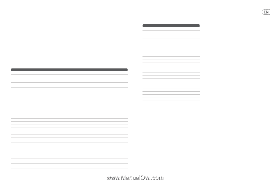
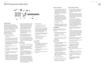
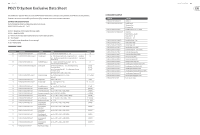
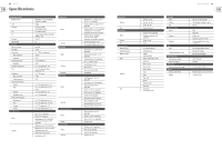
40 POLY D POLY D System Exclusive Data Sheet The "Synthtool.exe" application allows you to select the MIDI channel number and to set and adjust various parameters of the POLY D to suit your preferences. Parameters can also be accessed via MIDI system Exclusive (SysEx) commands. Please see the information shown below. SETTING VALUES VIA SYSEX Use the following data format to set global value using a SysEx message. F0 00 20 32 00 01 0c aa bb cc D0 ... Dn F7 00 20 32 = Manufacture SYSEX ID number (Behringer GmbH) 00 01 0c = Model ID for POLY D aa = Device ID: 00-0x7F (must match hardware device ID), or 0x00 to address all devices. bb = Packet Number cc = Sub packet number (maybe absent for some message). D0..Dn = Packet payload COMMAND TABLE Packet Number 00 0E 0F 10 11 12 14 15 16 17 19 1A 1B 20 21 22 23 24 25 26 7D SysEx Packet F0 00 20 32 00 01 0c DID 00 nn F7 F0 00 20 32 00 01 0c DID 0E 01 nn mm F7 F0 00 20 32 00 01 0c DID 0F nn F7 F0 00 20 32 00 01 0c DID 10 nn mm pp F7 F0 00 20 32 00 01 0c DID 11 nn mm F7 F0 00 20 32 00 01 0c DID 12 nn F7 F0 00 20 32 00 01 0c DID 14 nn mm F7 F0 00 20 32 00 01 0c DID 15 nn F7 F0 00 20 32 00 01 0c DID 16 nn F7 F0 00 20 32 00 01 0c DID 17 nn F7 F0 00 20 32 00 01 0c DID 19 nn F7 F0 00 20 32 00 01 0c DID 1A nn F7 F0 00 20 32 00 01 0c DID 1B nn F7 F0 00 20 32 00 01 0c DID 20 nn F7 F0 00 20 32 00 01 0c DID 21 nn F7 F0 00 20 32 00 01 0c DID 22 nn F7 F0 00 20 32 00 01 0c DID 23 nn F7 F0 00 20 32 00 01 0c DID 24 nn F7 F0 00 20 32 00 01 0c DID 25 nn F7 F0 00 20 32 00 01 0c DID 26 nn F7 F0 00 20 32 00 01 0c DID 7D F7 Functions Note Set device id (DID) n= DID to be set, range from [0-127], 0 ==any Set midi channel nn = Midi TX channel number to be set, range from [0-16], 0 == Any channel. mm = Midi RX channel number to be set, range from [0-16], 0 == Any channel. Default value [1]. Set MIDI IN Transpose nn = transpose value [0-24]. Transpose range is -12 to + 12, so 12 is no transpose. Default value [1]. Set velocity info nn = Key velocity of note on, 1 - 127 is a fixed value of velocity; 0 is dynamic velocity. mm = Key velocity of note off, 1 - 127 is a fixed value of velocity; 0 is dynamic velocity. pp = velocity Curve: 0 - soft, 1 - med, 2 - hard Set pitch bend range nn = Pitch bend range [0-24] , 0 - 2 octave. Ignore mm Set key priority [0-low, 1- high, 2-last] Set multi trigger nn = multi-trigger [0-off, 1-on]. Ignore mm Set modulation curve. nn = curve [0-soft, 1-Med, 2-hard] Set the Note @zero CV [0-127] Set the MIDI clock output nn = [0-OFF, 1-DIN, 2-USB, 3-BOTH] Set external clock polarity. nn = [0-FALLING, 1-RISSING], Set sync clock rate nn = [0 - 1 PPS, 1 - 2 PPQ, 2 - 24 PPQ, 3- 48 PPQ] Set sync clock source. nn = [0 - Internal, 1 - DIN, 2 - USB, 3 - TRIG] Modulation wheel range nn = [0-4] Set midi output of modulation wheel nn = [0-OFF, 1-DIN, 2-USB, 3-BOTH] Set midi output of pitch wheel nn = [0-OFF, 1-DIN, 2-USB, 3-BOTH] Set midi output of keyboard nn = [0-OFF, 1-DIN, 2-USB, 3-BOTH] Set midi output of keyboard after touch nn = [0-OFF, 1-DIN, 2-USB, 3-BOTH] Set midi output of sequencer nn = [0-OFF, 1-DIN, 2-USB, 3-BOTH] Set midi output of arpeggiator nn= [0-OFF, 1-DIN, 2-USB, 3-BOTH Restore factory settings Default [0] [1] [1] nn = [0], mm = [0], pp = [0] [12 -- 1 octave] [2-last] Nn = [nn=1, on] [0- soft] [0x24-C2] [3-BOTH] [1-RISING] [2-24 PPQ] [0 - Internal] [2-100%] [3-BOTH] [3-BOTH] [3-BOTH] [3-BOTH] [3-BOTH] [3-BOTH] COMMAND EXAMPLE COMMAND F0 00 20 32 00 01 0c DID 00 01 F7 F0 00 20 32 00 01 0c 00 0E 01 03 04 F7 F0 00 20 32 00 01 0c 00 0F 18 F7 F0 00 20 32 00 01 0c 00 10 00 30 00 F7 F0 00 20 32 00 01 0c 00 11 08 00 F7 F0 00 20 32 00 01 0c 00 12 01 F7 F0 00 20 32 00 01 0c 00 14 01 00 F7 F0 00 20 32 00 01 0c 00 15 02 F7 F0 00 20 32 00 01 0c 00 16 3C F7 F0 00 20 32 00 01 0c 00 17 00 F7 F0 00 20 32 00 01 0c 00 19 00 F7 F0 00 20 32 00 01 0c 00 1A 02 F7 F0 00 20 32 00 01 0c 00 1B 02 F7 F0 00 20 32 00 01 0c 00 20 02 F7 F0 00 20 32 00 01 0c 00 21 00 F7 F0 00 20 32 00 01 0c 00 22 01 F7 F0 00 20 32 00 01 0c 00 23 02 F7 F0 00 20 32 00 01 0c 00 24 03 F7 F0 00 20 32 00 01 0c 00 25 02 F7 F0 00 20 32 00 01 0c 00 26 01 F7 F0 00 20 32 00 01 0c 00 7D F7 FUNCTION Set DID as 1 Set MIDI channel: TX channel = 0x3, RX channel = 0x4 Set MIDI IN Transpose +12 ( +1 Octave) Set velocity: Velocity Note On = dynamic. Velocity Note Off = 48 Velocity Curve = Soft Set pitch bend range = 0x8 Set key priority = High Set multi trigger = ON Set modulation curve.= HARD Set the Note @zero CV = 0x3C (note C4) Set the MIDI clock output OFF Set external clock polarity FALLING.. Set sync clock rate 24PPQ Set sync clock source as USB Modulation wheel range 100% Set midi output of modulation wheel as OFF Set midi output of pitch wheel as DIN Set midi output of keyboard as USB Set midi output of keyboard after touch as BOTH Set midi output of sequencer as USB Set midi output of arpeggiator as DIN Restore factory settings Quick Start Guide 41
-
 1
1 -
2
-
3
-
4
-
5
-
6
-
7
-
8
-
9
-
10
-
11
-
12
-
13
-
14
-
15
-
 16
16 -
 17
17 -
 18
18 -
 19
19 -
 20
20 -
 21
21 -
 22
22 -
 23
23 -
 24
24 -
 25
25
 |
 |