Behringer POLY D Quick Start Guide - Page 8
Step 2: Controls
 |
View all Behringer POLY D manuals
Add to My Manuals
Save this manual to your list of manuals |
Page 8 highlights
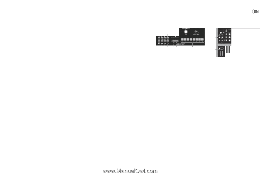
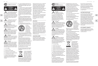
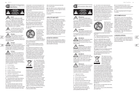
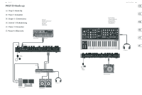
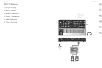
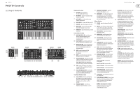
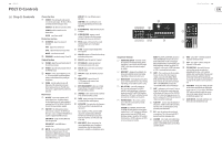
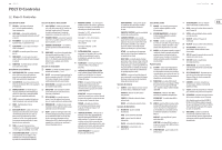
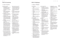
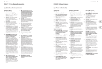
14 POLY D POLY D Controls (EN) Step 2: Controls Chorus Section (33) CHORUS I - this adds quality and a spatial sense to the audio output. The chorus effects are enhanced when listening in stereo. CHORUS II - this adds a deeper chorus effect. CHORUS I and II can both be on for a deeper effect. ON/OFF - turns Chorus on/off. Distortion Section (34) DISTORTION - adjust the amount of distortion. TONE - adjust the distortion tone. LEVEL - adjust the distortion output level. ON/OFF - turns Distortion on/off. (35) SEQUENCER - see details on page 15 and 38. Output Section (36) VOLUME - adjust the overall volume level of the synthesizer output. (37) PHONES - adjust the overall volume level of the PHONES output. (38) PHONES - connect your headphones to this ¼" TRS output. Make sure the headphone volume is turned down before putting on headphones. (39) POWER - turn the synthesizer on or off. Make sure all the connections are made before turning on the unit. The LED shows when power is applied and the synthesizer is turned on. Rear Panel (40) DC INPUT - connect the supplied 12V DC power adapter here. The power adapter can be plugged into an AC outlet capable of supplying from 100V to 240V at 50 Hz/60 Hz. Use only the power adapter supplied. (41) USB PORT - This USB type B jack allows connection to a computer. The POLY D will show up as a class-compliant USB MIDI device, capable of supporting MIDI in and out. USB MIDI IN - accepts incoming MIDI data from an application. USB MIDI OUT - sends MIDI data to an application. (42) MIDI IN - this 5-pin DIN jack receives MIDI data from an external source. This will commonly be a MIDI keyboard, an external hardware sequencer, a computer equipped with a MIDI interface, etc. MIDI OUT - this 5-pin DIN jack outputs MIDI data. MIDI THRU - this 5-pin DIN jack is used to pass through MIDI data received at the MIDI INPUT. (43) AFTER PRESSURE - adjust the after pressure CV output. (44) AFTER PRESSURE - outputs a control voltage (CV) based on the after pressure (pressing further down on a held note). (45) PITCH- outputs a CV based on the current pitch (by default, note C2 will output zero Volts). (46) V-TRIG - outputs a trigger voltage when a note is played. (47) VELOCITY- outputs a CV based on the velocity used when playing notes. (48) VELOCITY- adjust the velocity CV output. (49) EXT SIGNAL IN - connect any external line-level audio source to this input. (50) SYNC IN- allows connection of an external sync/clock signal. (51) SYNC OUT- outputs the internal sync/clock signal. (52) MAIN OUTPUT - connect these L/R ¼" TRS outputs to the inputs of your external equipment. (53) EXT V-TRIGGER INPUT - allows an external trigger voltage to be applied to trigger the filter and loudness contours. (54) LOUDNESS - allows connection of an external CV to control the loudness contour. (55) FILTER - allows connection of an external CV to control the filter cutoff frequency. (56) OSCILLATOR - this input allows the frequency of the four oscillators to be adjusted by an external CV. Note: LOUDNESS, FILTER, and OSCILLATOR can also be controlled using a Behringer FCV100 V2 or FC600 V2 expression pedal (with the CV polarity set to TRS, and using a TRS cord). (57) MOD SOURCE - allows connection of an external modulation source. If nothing is connected here, then the internal Noise generator is available as a modulation source. Quick Start Guide 15 (1) (2) (3)(4)(5) (10) (14) (6) (7)(8)(9) (11) (12) (13) (15) Sequencer Section (1) TEMPO/GATE LENGTH - this knob controls the sequencer and arpeggio tempo. During step editing, it also controls the GATE length. If SHIFT is held, then the knob also adjusts the SWING. (2) HOLD/REST - during pattern playback, this allows you to hold the current step. During step editing, it allows you to enter a rest. (3) RESET/ACCENT - during playback, this allows you to reset the pattern back to step 1. During step editing, you can add an accent to a step. (4) ARP (SET END) - press ARP and play any keys, to create an arpeggio. Press HOLD and ARP to hold the arpeggio. In Sequencer mode, pressing SHIFT and SET END together, followed by a STEP switch, will allow that step to become the end of the current pattern. (5) PATTERN (BANK) - This switch is used to access either the current pattern, or bank number, as follows: PATTERN: Press PATTERN, and one of the 8 LOCATION LEDs will show the current pattern number (from 1 to 8). To change to a different pattern number, keep the PATTERN switch held down and press any of the STEP switches (1 to 8), or press to increase the pattern number. BANK: Press SHIFT and PATTERN, and one of the 8 LOCATION LEDs will show the current bank number (from 1 to 8). To change to a different bank number, keep both SHIFT and BANK held down, and press any of the STEP switches (1 to 8), or press to increase the bank number. (6) SHIFT - This is used to access the secondary features of some of the other sequencer controls, such as SET END, BANK, SWING, KYDB, and STEP. Hold down SHIFT and the other switch at the same time. For example SHIFT + PATTERN (BANK) will show the current BANK number in the LOCATOR LEDs. (7) PAGE - each pattern can be up to 32 steps in length. This switch allows you to show each of the 4 pages of 8 steps each. The LOCATION LEDs 1 to 4, show which page you are on. If a pattern is playing, the STEP LEDs will show the steps in use on the current page. (8) PLAY/STOP - starts or stops the playback of the pattern. If SHIFT is held at the same time, then this is the start of the pattern saving procedure, described below. (9) REC - press this to begin the recording of a new pattern. This is also used with SHIFT during the pattern saving procedure. (10) LOCATION - these multi-colored LEDS show various details, such as the current PATTERN number, current BANK number, current PAGE, and GATE LENGTH. (11) KYBD - press SHIFT + KYBD to change the sequencer to keyboard mode. (12) STEP - press SHIFT + STEP to change the sequencer to STEP mode. (13) STEP SWITCHES - these multi-function switches allow you to view and select individual pattern steps, select a pattern number, select a pattern bank. They are used during recording of a pattern to show the current step. Active steps are illuminated with a steady red LED, and the current step flashes red. (14) GLIDE KNOB - during step editing, this knob can be used to add a Ratchet by splitting the current step into 1, 2, 3, or 4 parts. Hold down SHIFT and turn the knob to split the current step into the number of parts shown by the LOCATOR LEDs (yellow) 1 to 4. (15) GLIDE SWITCH - the GLIDE switch does not have to be on for the Ratchet to work.
-
 1
1 -
2
-
 3
3 -
 4
4 -
 5
5 -
 6
6 -
 7
7 -
 8
8 -
 9
9 -
 10
10 -
 11
11 -
 12
12 -
 13
13 -
14
-
15
-
16
-
17
-
18
-
19
-
20
-
21
-
22
-
23
-
24
-
25
 |
 |