Bosch NWD-495V03-20P Operating Instructions - Page 21

Disassembly
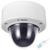
Page 21 highlights

FlexiDomeDN IP Disassembly | en 21 2 Disassembly The camera/housing unit consists of the following parts: Mounting plate Camera module and mounting base Inner liner Trim ring and dome Fig. 2.1 Exploded view CAUTION! ! Installation should only be performed by qualified service personnel in accordance with the National Electrical Code or applicable local codes. CAUTION! ! The camera module is a sensitive device and must be handled carefully. Do not drop when disassembling the unit. To disassemble the unit proceed as follows: 1. Using the special screwdriver bit, loosen the three tamper- resistant screws in the trim ring (the screws remain in place). 2. Remove the trim ring with dome by pulling it off of the base. 3. Remove the inner liner by pulling it off of the base. 4. Loosen the three Phillips captive screws until the mounting plate separates from the body Bosch Security Systems Operating Instructions V 1.0 | 2006.12

  • 1
  • 2
  • 3
  • 4
  • 5
  • 6
  • 7
  • 8
  • 9
  • 10
  • 11
  • 12
  • 13
  • 14
  • 15
  • 16
  • 17
  • 18
  • 19
  • 20
  • 21
  • 22
  • 23
  • 24
  • 25
  • 26
  • 27
  • 28
  • 29
  • 30
  • 31
  • 32
  • 33
  • 34
  • 35
  • 36
  • 37
  • 38
  • 39
  • 40
  • 41
  • 42
  • 43
  • 44
  • 45
  • 46
  • 47
  • 48
  • 49
  • 50
  • 51
  • 52
  • 53
  • 54
  • 55
  • 56
  • 57
  • 58
  • 59
  • 60
  • 61
  • 62
  • 63
  • 64
  • 65
  • 66
  • 67
  • 68
  • 69
  • 70
  • 71
  • 72
  • 73
  • 74
  • 75
  • 76
  • 77
  • 78
  • 79
  • 80
  • 81
  • 82
  • 83
  • 84
  • 85
  • 86
  • 87
  • 88
  • 89
  • 90
  • 91
  • 92
  • 93
  • 94
  • 95
  • 96
  • 97
  • 98
  • 99
  • 100
  • 101
  • 102
  • 103
  • 104
  • 105
  • 106
  • 107
  • 108
  • 109
  • 110

FlexiDome
DN
IP
Disassembly | en
21
Bosch Security Systems
Operating Instructions
V 1.0 | 2006.12
2
Disassembly
The camera/housing unit consists of the following parts:
Fig. 2.1
Exploded view
To disassemble the unit proceed as follows:
1.
Using the special screwdriver bit, loosen the three tamper-
resistant screws in the trim ring (the screws remain in
place).
2.
Remove the trim ring with dome by pulling it off of the
base.
3.
Remove the inner liner by pulling it off of the base.
4.
Loosen the three Phillips captive screws until the mount-
ing plate separates from the body
Mounting plate
Camera module and mounting base
Inner liner
Trim ring and dome
!
CAUTION!
Installation should only be performed by qualified service
personnel in accordance with the National Electrical Code or
applicable local codes.
!
CAUTION!
The camera module is a sensitive device and must be handled
carefully. Do not drop when disassembling the unit.