Bosch NWD-495V03-20P Operating Instructions - Page 25

Camera set-up
Page 25 highlights

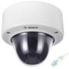
FlexiDomeDN IP 4 Camera set-up Camera set-up | en 25 4.1 Camera positioning You can connect a monitor to the miniature 2.5mm jack socket on the printed circuit board to help set up the camera. This socket provides a composite video signal (with sync). An optional cable (code number S1460) is available for making this connection. Focus Focal length Navigation switches Thumbwheels Monitor jack Fig. 4.1 Positioning The physical default position of the camera is that the top of the image corresponds to the indication TOP. The camera module position can be adjusted along three axes. When adjusting the camera position ensure that the picture display on the monitor is level. Set the camera to the desired position by performing the following steps: - For horizontal adjustment (pan), rotate the camera module in the base. Do not rotate more than 360°. - For vertical adjustment (tilt), loosen thumbscrews, posi- tion camera, then gently tighten thumbscrews to secure camera. Bosch Security Systems Operating Instructions V 1.0 | 2006.12

  • 1
  • 2
  • 3
  • 4
  • 5
  • 6
  • 7
  • 8
  • 9
  • 10
  • 11
  • 12
  • 13
  • 14
  • 15
  • 16
  • 17
  • 18
  • 19
  • 20
  • 21
  • 22
  • 23
  • 24
  • 25
  • 26
  • 27
  • 28
  • 29
  • 30
  • 31
  • 32
  • 33
  • 34
  • 35
  • 36
  • 37
  • 38
  • 39
  • 40
  • 41
  • 42
  • 43
  • 44
  • 45
  • 46
  • 47
  • 48
  • 49
  • 50
  • 51
  • 52
  • 53
  • 54
  • 55
  • 56
  • 57
  • 58
  • 59
  • 60
  • 61
  • 62
  • 63
  • 64
  • 65
  • 66
  • 67
  • 68
  • 69
  • 70
  • 71
  • 72
  • 73
  • 74
  • 75
  • 76
  • 77
  • 78
  • 79
  • 80
  • 81
  • 82
  • 83
  • 84
  • 85
  • 86
  • 87
  • 88
  • 89
  • 90
  • 91
  • 92
  • 93
  • 94
  • 95
  • 96
  • 97
  • 98
  • 99
  • 100
  • 101
  • 102
  • 103
  • 104
  • 105
  • 106
  • 107
  • 108
  • 109
  • 110

FlexiDome
DN
IP
Camera set-up | en
25
Bosch Security Systems
Operating Instructions
V 1.0 | 2006.12
4
Camera set-up
4.1
Camera positioning
You can connect a monitor to the miniature 2.5mm jack socket
on the printed circuit board to help set up the camera. This
socket provides a composite video signal (with sync). An
optional cable (code number S1460) is available for making this
connection.
Fig. 4.1
Positioning
The physical default position of the camera is that the top of
the image corresponds to the indication TOP.
The camera module position can be adjusted along three axes.
When adjusting the camera position ensure that the picture dis-
play on the monitor is level. Set the camera to the desired posi-
tion by performing the following steps:
For horizontal adjustment (pan), rotate the camera module
in the base. Do not rotate more than 360°.
For vertical adjustment (tilt), loosen thumbscrews, posi-
tion camera, then gently tighten thumbscrews to secure
camera.
Navigation switches
Thumbwheels
Monitor jack
Focal length
Focus