Bowflex Xtreme 2 Assembly Manual - Page 13
Step 14, Attach Upper Lat Tower to the Lower Assembly, Step 15, Attach the Lat Pulley Housing
 |
View all Bowflex Xtreme 2 manuals
Add to My Manuals
Save this manual to your list of manuals |
Page 13 highlights
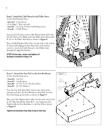
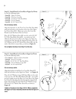
Step 14: Attach Upper Lat Tower to the Lower Assembly Locate the following items: • From Step 13 - Upper Lat Tower Assembly • From Step 11 - Main Assembly • Item #F - (3) 3/8" X 3/4" Hex Head Bolts • Item #O - (3) 3/8" Washers Figure 14 For your safety, use two people to complete this step. Position the Upper Lat Tower Assembly over the Main Assembly as shown in Figure 14. Insert the base of the Upper Main Assembly Lat Tower all the way into the top of the Lower Lat Tower on the O Main Assembly. Align all bolt holes and secure by placing using (1) 3/8" Washer (Item #O) over (1) 3/8" X 3/4" Hex Head Bolt (Item #F) in the upper, back hole. Then place (2) 3/8" Washers over (2) 3/8" X 3/4" Hex Head Bolts - one washer per bolt, and loosely secure the lower, side holes, as shown in Figure 14. Do not tighten hardware from Step 14 at this time. Step 15: Attach the Lat Pulley Housing Locate the following items: • Item #28 - Lat Pulley Housing • From Step 14 - Main Assembly • Item #G - (2) 3/8" X 1" Hex Head Bolts • Item #O - (2) 3/8" Washers Remove the plastic cap from the 3/8" X 4 1/2" Bolt (Item #AA) already installed on the back of the Lat Pulley Housing. Tighten this bolt until it is "finger tight" - you will be removing and re-installing this bolt during Step 17. Place the brackets of the Lat Pulley Housing (Item #28) on either side of the Lat Tower, aligning the bolt holes in the bracket with the bolt holes in the Lat Tower, as shown in Figure 15. Place (2) 3/8" Washers (Item #O) over the ends of (2) 3/8" X 1" Hex Head Bolts (Item #G) - one washer per bolt. Secure the Lat Pulley Housing to the Lat Tower by screwing the bolts loosely into the aligned holes as shown in Figure 15. Do not tighten hardware from Step 15 at this time. Figure 15 O G 11 Upper Lat Tower Assembly F 28 AA
-
 1
1 -
2
-
3
-
4
-
5
-
6
-
7
-
 8
8 -
 9
9 -
 10
10 -
 11
11 -
 12
12 -
 13
13 -
 14
14 -
 15
15 -
 16
16 -
 17
17 -
 18
18 -
19
-
20
-
21
-
22
-
23
 |
 |
