Brother International 3450CN User Guide - Page 164
of the Lower Tray Unit. Push, Tray Unit.
 |
UPC - 012502601463
View all Brother International 3450CN manuals
Add to My Manuals
Save this manual to your list of manuals |
Page 164 highlights
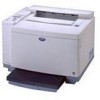
CHAPTER 6 OPTIONS 4. Remove the Back caps (2 pieces) of the Lower Tray Unit. Push down lightly on the caps and slide them to the rear of the printer to remove them. 5. Use the handholds of the Duplex Unit to lift the Duplex Unit up. Fig. 6-12 Fig. 6-13 Note Ensure that the Duplex Cover Top Assembly is aligned and latched straight with the lower part of the duplex unit. 6. Insert the fixing pins at the sides of the Duplex Unit into the installation grooves in the Lower Tray Unit. Fig. 6-14 Note Make sure that the Rear Cover of the Lower Tray Unit is closed. 6-8
-
 1
1 -
2
-
3
-
4
-
5
-
6
-
7
-
8
-
9
-
10
-
11
-
12
-
13
-
14
-
15
-
16
-
17
-
18
-
19
-
20
-
21
-
22
-
23
-
24
-
25
-
26
-
27
-
28
-
29
-
30
-
31
-
32
-
33
-
34
-
35
-
36
-
37
-
38
-
39
-
40
-
41
-
42
-
43
-
44
-
45
-
46
-
47
-
48
-
49
-
50
-
51
-
52
-
53
-
54
-
55
-
56
-
57
-
58
-
59
-
60
-
61
-
62
-
63
-
64
-
65
-
66
-
67
-
68
-
69
-
70
-
71
-
72
-
73
-
74
-
75
-
76
-
77
-
78
-
79
-
80
-
81
-
82
-
83
-
84
-
85
-
86
-
87
-
88
-
89
-
90
-
91
-
92
-
93
-
94
-
95
-
96
-
97
-
98
-
99
-
100
-
101
-
102
-
103
-
104
-
105
-
106
-
107
-
108
-
109
-
110
-
111
-
112
-
113
-
114
-
115
-
116
-
117
-
118
-
119
-
120
-
121
-
122
-
123
-
124
-
125
-
126
-
127
-
128
-
129
-
130
-
131
-
132
-
133
-
134
-
135
-
136
-
137
-
138
-
139
-
140
-
141
-
142
-
143
-
144
-
145
-
146
-
147
-
148
-
149
-
150
-
151
-
152
-
153
-
154
-
155
-
156
-
157
-
158
-
 159
159 -
 160
160 -
 161
161 -
 162
162 -
 163
163 -
 164
164 -
 165
165 -
 166
166 -
 167
167 -
 168
168 -
 169
169 -
170
-
171
-
172
-
173
-
174
-
175
-
176
-
177
-
178
-
179
-
180
-
181
-
182
-
183
-
184
-
185
-
186
-
187
-
188
-
189
-
190
-
191
-
192
-
193
-
194
-
195
-
196
-
197
-
198
-
199
-
200
-
201
-
202
-
203
-
204
-
205
-
206
-
207
-
208
-
209
-
210
-
211
-
212
-
213
-
214
-
215
-
216
-
217
-
218
-
219
-
220
-
221
-
222
-
223
-
224
-
225
-
226
-
227
 |
 |

CHAPTER 6 OPTIONS
6-8
4.
Remove the Back caps (2 pieces)
of the Lower Tray Unit. Push
down lightly on the caps and slide
them to the rear of the printer to
remove them.
Fig. 6-12
5.
Use the handholds of the Duplex
Unit to lift the Duplex Unit up.
Fig. 6-13
Note
Ensure that the Duplex Cover Top Assembly is aligned and latched
straight with the lower part of the duplex unit.
6.
Insert the fixing pins at the sides
of the Duplex Unit into the
installation grooves in the Lower
Tray Unit.
Fig. 6-14
Note
Make sure that the Rear Cover of the Lower Tray Unit is closed.