Brother International 3450CN User Guide - Page 173
Fit the 4 HD-6G/HD-EX shoulder, See
 |
UPC - 012502601463
View all Brother International 3450CN manuals
Add to My Manuals
Save this manual to your list of manuals |
Page 173 highlights
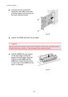
5. Fit the 4 HD-6G/HD-EX shoulder screws into the 4 holes of the main controller board, and then secure the shoulder screws with the screws provided from the rear of the PCB. 6. Connect the flat cable to the main controller board. 7. Install the main controller board into the printer by sliding it into the guide rails. CHAPTER 6 OPTIONS Fig. 6-23 Fig. 6-24 Fig. 6-25 8. Secure the main controller board with the 2 screws. 9. Reconnect the interface cable to the printer. Plug the power cord into the AC outlet, and then turn on the printer. 10. Format the HD-6G/HD-EX from the control panel. See Chapter 4 for details. 6-17
-
 1
1 -
2
-
3
-
4
-
5
-
6
-
7
-
8
-
9
-
10
-
11
-
12
-
13
-
14
-
15
-
16
-
17
-
18
-
19
-
20
-
21
-
22
-
23
-
24
-
25
-
26
-
27
-
28
-
29
-
30
-
31
-
32
-
33
-
34
-
35
-
36
-
37
-
38
-
39
-
40
-
41
-
42
-
43
-
44
-
45
-
46
-
47
-
48
-
49
-
50
-
51
-
52
-
53
-
54
-
55
-
56
-
57
-
58
-
59
-
60
-
61
-
62
-
63
-
64
-
65
-
66
-
67
-
68
-
69
-
70
-
71
-
72
-
73
-
74
-
75
-
76
-
77
-
78
-
79
-
80
-
81
-
82
-
83
-
84
-
85
-
86
-
87
-
88
-
89
-
90
-
91
-
92
-
93
-
94
-
95
-
96
-
97
-
98
-
99
-
100
-
101
-
102
-
103
-
104
-
105
-
106
-
107
-
108
-
109
-
110
-
111
-
112
-
113
-
114
-
115
-
116
-
117
-
118
-
119
-
120
-
121
-
122
-
123
-
124
-
125
-
126
-
127
-
128
-
129
-
130
-
131
-
132
-
133
-
134
-
135
-
136
-
137
-
138
-
139
-
140
-
141
-
142
-
143
-
144
-
145
-
146
-
147
-
148
-
149
-
150
-
151
-
152
-
153
-
154
-
155
-
156
-
157
-
158
-
159
-
160
-
161
-
162
-
163
-
164
-
165
-
166
-
167
-
 168
168 -
 169
169 -
 170
170 -
 171
171 -
 172
172 -
 173
173 -
 174
174 -
 175
175 -
 176
176 -
 177
177 -
 178
178 -
179
-
180
-
181
-
182
-
183
-
184
-
185
-
186
-
187
-
188
-
189
-
190
-
191
-
192
-
193
-
194
-
195
-
196
-
197
-
198
-
199
-
200
-
201
-
202
-
203
-
204
-
205
-
206
-
207
-
208
-
209
-
210
-
211
-
212
-
213
-
214
-
215
-
216
-
217
-
218
-
219
-
220
-
221
-
222
-
223
-
224
-
225
-
226
-
227
 |
 |

CHAPTER 6 OPTIONS
6-17
5.
Fit the 4 HD-6G/HD-EX shoulder
screws into the 4 holes of the
main controller board, and then
secure the shoulder screws with
the screws provided from the rear
of the PCB.
Fig. 6-23
6.
Connect the flat cable to the main
controller board.
Fig. 6-24
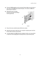
7.
Install the main controller board
into the printer by sliding it into
the guide rails.
Fig. 6-25
8.
Secure the main controller board with the 2 screws.
9.
Reconnect the interface cable to the printer.
Plug the power cord into the
AC outlet, and then turn on the printer.
10.
Format the HD-6G/HD-EX from the control panel.
See Chapter 4 for
details.