Brother International 3450CN User Guide - Page 176
notches on the DIMM with the, against the back edge. Align
 |
UPC - 012502601463
View all Brother International 3450CN manuals
Add to My Manuals
Save this manual to your list of manuals |
Page 176 highlights
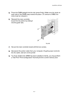
CHAPTER 6 OPTIONS 2. Unscrew the two screws that secure the rear plate of the main controller board, and then pull out the main controller board. 3. Unpack the DIMM and hold it by its edges. Fig. 6-26 ! Caution Do not touch the memory chips and the surface of the main controller board. If static electricity collects, it may damage these electrical parts. 4. Hold the DIMM with your fingers on the side edges and thumb against the back edge. Align the notches on the DIMM with the DIMM slot. (Check that the locks on each side of the DIMM slot are open, or outward). Fig. 6-27 6-20
-
 1
1 -
2
-
3
-
4
-
5
-
6
-
7
-
8
-
9
-
10
-
11
-
12
-
13
-
14
-
15
-
16
-
17
-
18
-
19
-
20
-
21
-
22
-
23
-
24
-
25
-
26
-
27
-
28
-
29
-
30
-
31
-
32
-
33
-
34
-
35
-
36
-
37
-
38
-
39
-
40
-
41
-
42
-
43
-
44
-
45
-
46
-
47
-
48
-
49
-
50
-
51
-
52
-
53
-
54
-
55
-
56
-
57
-
58
-
59
-
60
-
61
-
62
-
63
-
64
-
65
-
66
-
67
-
68
-
69
-
70
-
71
-
72
-
73
-
74
-
75
-
76
-
77
-
78
-
79
-
80
-
81
-
82
-
83
-
84
-
85
-
86
-
87
-
88
-
89
-
90
-
91
-
92
-
93
-
94
-
95
-
96
-
97
-
98
-
99
-
100
-
101
-
102
-
103
-
104
-
105
-
106
-
107
-
108
-
109
-
110
-
111
-
112
-
113
-
114
-
115
-
116
-
117
-
118
-
119
-
120
-
121
-
122
-
123
-
124
-
125
-
126
-
127
-
128
-
129
-
130
-
131
-
132
-
133
-
134
-
135
-
136
-
137
-
138
-
139
-
140
-
141
-
142
-
143
-
144
-
145
-
146
-
147
-
148
-
149
-
150
-
151
-
152
-
153
-
154
-
155
-
156
-
157
-
158
-
159
-
160
-
161
-
162
-
163
-
164
-
165
-
166
-
167
-
168
-
169
-
170
-
 171
171 -
 172
172 -
 173
173 -
 174
174 -
 175
175 -
 176
176 -
 177
177 -
 178
178 -
 179
179 -
 180
180 -
 181
181 -
182
-
183
-
184
-
185
-
186
-
187
-
188
-
189
-
190
-
191
-
192
-
193
-
194
-
195
-
196
-
197
-
198
-
199
-
200
-
201
-
202
-
203
-
204
-
205
-
206
-
207
-
208
-
209
-
210
-
211
-
212
-
213
-
214
-
215
-
216
-
217
-
218
-
219
-
220
-
221
-
222
-
223
-
224
-
225
-
226
-
227
 |
 |

CHAPTER 6 OPTIONS
6-20
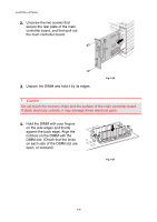
2.
Unscrew the two screws that
secure the rear plate of the main
controller board, and then pull out
the main controller board.
Fig. 6-26
3.
Unpack the DIMM and hold it by its edges.
!
Caution
Do not touch the memory chips and the surface of the main controller board.
If static electricity collects, it may damage these electrical parts.
4.
Hold the DIMM with your fingers
on the side edges and thumb
against the back edge. Align the
notches on the DIMM with the
DIMM slot. (Check that the locks
on each side of the DIMM slot are
open, or outward).
Fig. 6-27