Brother International BAS-705 Instruction Manual - English - Page 8
-4.Installing the auxiliary legs, 2-5. Checking the loop cutting, above the floor.
 |
View all Brother International BAS-705 manuals
Add to My Manuals
Save this manual to your list of manuals |
Page 8 highlights
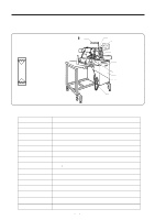
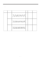
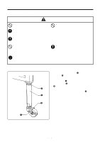
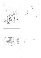
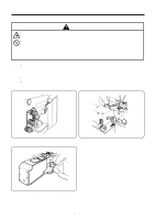
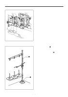
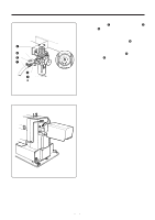
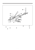
2-4.Installing the auxiliary legs q w ɹ u i t r e yɹɹɹɹ 2. PREPARATION 1. Remove the two auxiliary legs w which are secured to leg frame q. 2. Re-install the two removed legs w as shown in the illustration at left, and secure them with the bolts e, spring washers r and flat washers t which were removed before. 3. Loosen the nuts u (in two places) and turn the level adjusters i to adjust the height of the casters y above the floor. NOTE: After adjusting, securely tighten the nut u. 2-5. Checking the loop cutting q w No 1 NOTE: At the time of shipment from the factory, the Vcutting cylinder is in the lock position (flat-end cutting). ˙ Changing to V-shaped cutting 1. Remove the q, set the knife stopper w to the posi- tion shown in the illustration at left, and then re-tighten the bolt q. 2. Check that DIP switch No.1-2 on the panel is set to "ON". ʕ 5 ʕ B A S -705
-
 1
1 -
2
-
 3
3 -
 4
4 -
 5
5 -
 6
6 -
 7
7 -
 8
8 -
 9
9 -
 10
10 -
 11
11 -
 12
12 -
 13
13 -
14
-
15
-
16
-
17
-
18
-
19
-
20
-
21
-
22
-
23
-
24
-
25
-
26
-
27
-
28
-
29
-
30
-
31
-
32
-
33
-
34
-
35
-
36
-
37
-
38
-
39
-
40
-
41
-
42
-
43
-
44
-
45
-
46
-
47
-
48
-
49
-
50
-
51
-
52
-
53
-
54
-
55
-
56
-
57
-
58
-
59
-
60
-
61
-
62
-
63
-
64
-
65
-
66
-
67
-
68
-
69
-
70
-
71
-
72
-
73
-
74
-
75
-
76
-
77
-
78
-
79
-
80
-
81
-
82
-
83
-
84
-
85
-
86
-
87
-
88
-
89
 |
 |
