Canon LV-X2 Owners Manual - Page 43
Appendix, Configurations Of The Terminals
 |
View all Canon LV-X2 manuals
Add to My Manuals
Save this manual to your list of manuals |
Page 43 highlights
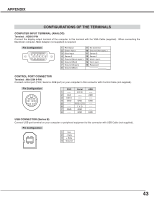
APPENDIX CONFIGURATIONS OF THE TERMINALS COMPUTER INPUT TERMINAL (ANALOG) Terminal : HDB15-PIN Connect the display output terminal of the computer to this terminal with the VGA Cable (supplied). When connecting the Macintosh computer, MAC Adapter (not supplied) is required. Pin Configuration 54 32 1 10 9 8 7 6 15 14 13 12 11 1 Red Input 9 No Connect 2 Green Input 10 Ground (Vert.sync.) 3 Blue Input 11 Sense 0 4 Sense 2 12 Sense 1 5 Ground (Horiz.sync.) 13 Horiz. sync. 6 Ground (Red) 14 Vert. sync. 7 Ground (Green) 15 Reserved 8 Ground (Blue) CONTROL PORT CONNECTOR Terminal : Mini DIN 8-PIN Connect control port (PS/2, Serial or ADB port) on your computer to this connector with Control Cable (not supplied). Pin Configuration 876 5 43 21 PS/2 Serial ADB 1 ----- R X D ----- 2 CLK ----- ADB 3 DATA ----- ----- 4 GND GND GND 5 ----- RTS / CTS ----- 6 ----- T X D ----- 7 GND GND ----- 8 ----- GND GND USB CONNECTOR (Series B) Connect USB port terminal on your computer or peripheral equipment to this connector with USB Cable (not supplied). Pin Configuration 21 34 1 Vcc 2 - Data 3 + Data 4 Ground 43
-
 1
1 -
2
-
3
-
4
-
5
-
6
-
7
-
8
-
9
-
10
-
11
-
12
-
13
-
14
-
15
-
16
-
17
-
18
-
19
-
20
-
21
-
22
-
23
-
24
-
25
-
26
-
27
-
28
-
29
-
30
-
31
-
32
-
33
-
34
-
35
-
36
-
37
-
 38
38 -
 39
39 -
 40
40 -
 41
41 -
 42
42 -
 43
43 -
 44
44
 |
 |
