Canon MF6530 Service Manual - Page 139
Control Panel, 2 Fan
 |
UPC - 013803056037
View all Canon MF6530 manuals
Add to My Manuals
Save this manual to your list of manuals |
Page 139 highlights
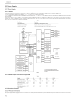
9.1 Control Panel 9.1.1 Outline The machine's control panel consists of the following PCBs, and is controlled by the ASIC of the image processor PCB. Image processor PCB Control panel PCB CPU Chapter 9 0012-7126 ASIC Key SW LED LCD F-9-1 9.2 Fan 9.2.1 Outline 0011-5769 This machine has a fan on the rear side to discharge the hot air around the fixing unit and cool the laser scanner unit and electric elements on PCBs. The fan is controlled by the CPU on the DC controller PCB. Its operating conditions are as follows: 1. During normal rotation, in the fixing cleaning mode (user mode), or after paper has reached the registration clutch 2. During transfer roller cleaning (user mode) or after operation of the main motor 1. After post-rotation, after completion of the cleaning mode, or 30 seconds after stop of the main motor 2. After stop of the main motor due to opening of a door or occurrence of a jam or other failures The CPU on the DC controller CPU outputs a Fan Drive signal (FANON = 'H') to turn the fan. The CPU judges that a fan failure has occurred if it detects a Fan Lock Detection signal (FANLOCK = 'H') during fan rotation. FM1 Fixing unit F-9-2 9-1
-
 1
1 -
2
-
3
-
4
-
5
-
6
-
7
-
8
-
9
-
10
-
11
-
12
-
13
-
14
-
15
-
16
-
17
-
18
-
19
-
20
-
21
-
22
-
23
-
24
-
25
-
26
-
27
-
28
-
29
-
30
-
31
-
32
-
33
-
34
-
35
-
36
-
37
-
38
-
39
-
40
-
41
-
42
-
43
-
44
-
45
-
46
-
47
-
48
-
49
-
50
-
51
-
52
-
53
-
54
-
55
-
56
-
57
-
58
-
59
-
60
-
61
-
62
-
63
-
64
-
65
-
66
-
67
-
68
-
69
-
70
-
71
-
72
-
73
-
74
-
75
-
76
-
77
-
78
-
79
-
80
-
81
-
82
-
83
-
84
-
85
-
86
-
87
-
88
-
89
-
90
-
91
-
92
-
93
-
94
-
95
-
96
-
97
-
98
-
99
-
100
-
101
-
102
-
103
-
104
-
105
-
106
-
107
-
108
-
109
-
110
-
111
-
112
-
113
-
114
-
115
-
116
-
117
-
118
-
119
-
120
-
121
-
122
-
123
-
124
-
125
-
126
-
127
-
128
-
129
-
130
-
131
-
132
-
133
-
 134
134 -
 135
135 -
 136
136 -
 137
137 -
 138
138 -
 139
139 -
 140
140 -
 141
141 -
 142
142 -
 143
143 -
 144
144 -
145
-
146
-
147
-
148
-
149
-
150
-
151
-
152
-
153
-
154
-
155
-
156
-
157
-
158
-
159
-
160
-
161
-
162
-
163
-
164
-
165
-
166
-
167
-
168
-
169
-
170
-
171
-
172
-
173
-
174
-
175
-
176
-
177
-
178
-
179
-
180
-
181
-
182
-
183
-
184
-
185
-
186
-
187
-
188
-
189
-
190
-
191
-
192
-
193
-
194
-
195
-
196
-
197
-
198
-
199
-
200
-
201
-
202
-
203
-
204
-
205
-
206
-
207
-
208
-
209
-
210
-
211
-
212
-
213
-
214
-
215
-
216
-
217
-
218
-
219
-
220
-
221
-
222
-
223
-
224
-
225
-
226
-
227
-
228
-
229
-
230
-
231
-
232
-
233
-
234
-
235
-
236
-
237
-
238
-
239
-
240
-
241
-
242
-
243
-
244
-
245
-
246
-
247
-
248
-
249
-
250
 |
 |
