Canon MF6530 Service Manual - Page 140
Power Supply
 |
UPC - 013803056037
View all Canon MF6530 manuals
Add to My Manuals
Save this manual to your list of manuals |
Page 140 highlights
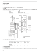
Chapter 9 9.3 Power Supply 9.3.1 Power Supply 9.3.1.1 Outline 0011-5770 When the main power switch (SW1) is turned on, AC power is supplied to the low-voltage power supply circuit in the power supply PCB. The low-voltage power supply circuit supplies +3.3 V, +5 V, and +24 V to operate the machine. +24 V is supplied to the motors, fan, electromagnetic clutch, solenoid, etc. +5 V and +3.3 V are supplied to the DC controller PCB, image processor PCB, anlog processor PCB. There are two types of +24 V voltages: +24 VR which is normaly supplied from the low voltage power supply and +24 VU which is cut off when the left door is opened. The +24VU is supplied to the DC controller PCB and main motor. The +24 VU also plays the role of a door open detection signal (DOPEN). This signal allows the CPU to detect that the left door has opened. T-9-1 Part Name Power supply PCB Main power switch (SW1) Interlock switch (SW2) Function Generates DC power from AC power. Supplies AC power to the power supply PCB. Detects opening/closing of the left door and cuts off +24 VR. P1 Power supply PCB SW1 F1 To NCU PCB +3.3VR +24VR Relay PCB +24VR Clutches +24VR Fan +24VR Solenoids +3.3VR Sensors NF F2 Low-voltage power supply circuit +3.3Vcircuit +5Vcircuit +24Vcircuit ADF ADF motor ADF solenoids ADF sensors +24V +24V +3.3V Reader unit CS unit CS hp sensor Reader motor +24V +3.3V +3.3V +24V +24VR +5VR +3.3VR +3.3V +5V +3.3VR DC controller PCB +5VR +24VR +24VR +24VU +24VU +5VR +3.3VR +24VR +3.3VR +24VR Laser scanner unit Interlock switch (SW2) Main motor Sensors Cassette unit*3 Analog processor PCB +3.3V +5V Image processor PCB +5V +5VS Control panel +3.3V +5V Modem PCB*1 +3.3V +5V +3.3VS +5VS Network PCB*2 Mojular jack PCB*1 NCU PCB*1 F-9-3 *1 : Only if equipped with Fax functions. *2 : Only if equipped with Network functions. *3 : Option 9.3.1.2 Rated Output of the Power Supply PCB T-9-2 0011-5771 Output 24VR Rated output voltage 24V Output voltage tolerance +10%, -5% Rated output current 4.5A Overcurrent protection 7.0A trigger current Overvoltage protection 32.5V trigger voltage 9.3.2 Protection Function 5V 5.1V +3%, -4% 0.3A 4.0A 8.0V 5VR 5.1V +3%, -4% 0.7A 2.0A 8.0V 3.3V 3.4V +3%, -3% 2.4A 3.7A 5.5V 3.3VR 3.4V +3%, -3% 0.8A 2.0A 5.5V 9.3.2.1 Protective Functions 0011-5772 The power supply PCB is equipped with an over-current/over-voltage protection mechanism to prevent damage to the power circuit in the event of an over-current 9-2
-
 1
1 -
2
-
3
-
4
-
5
-
6
-
7
-
8
-
9
-
10
-
11
-
12
-
13
-
14
-
15
-
16
-
17
-
18
-
19
-
20
-
21
-
22
-
23
-
24
-
25
-
26
-
27
-
28
-
29
-
30
-
31
-
32
-
33
-
34
-
35
-
36
-
37
-
38
-
39
-
40
-
41
-
42
-
43
-
44
-
45
-
46
-
47
-
48
-
49
-
50
-
51
-
52
-
53
-
54
-
55
-
56
-
57
-
58
-
59
-
60
-
61
-
62
-
63
-
64
-
65
-
66
-
67
-
68
-
69
-
70
-
71
-
72
-
73
-
74
-
75
-
76
-
77
-
78
-
79
-
80
-
81
-
82
-
83
-
84
-
85
-
86
-
87
-
88
-
89
-
90
-
91
-
92
-
93
-
94
-
95
-
96
-
97
-
98
-
99
-
100
-
101
-
102
-
103
-
104
-
105
-
106
-
107
-
108
-
109
-
110
-
111
-
112
-
113
-
114
-
115
-
116
-
117
-
118
-
119
-
120
-
121
-
122
-
123
-
124
-
125
-
126
-
127
-
128
-
129
-
130
-
131
-
132
-
133
-
134
-
 135
135 -
 136
136 -
 137
137 -
 138
138 -
 139
139 -
 140
140 -
 141
141 -
 142
142 -
 143
143 -
 144
144 -
 145
145 -
146
-
147
-
148
-
149
-
150
-
151
-
152
-
153
-
154
-
155
-
156
-
157
-
158
-
159
-
160
-
161
-
162
-
163
-
164
-
165
-
166
-
167
-
168
-
169
-
170
-
171
-
172
-
173
-
174
-
175
-
176
-
177
-
178
-
179
-
180
-
181
-
182
-
183
-
184
-
185
-
186
-
187
-
188
-
189
-
190
-
191
-
192
-
193
-
194
-
195
-
196
-
197
-
198
-
199
-
200
-
201
-
202
-
203
-
204
-
205
-
206
-
207
-
208
-
209
-
210
-
211
-
212
-
213
-
214
-
215
-
216
-
217
-
218
-
219
-
220
-
221
-
222
-
223
-
224
-
225
-
226
-
227
-
228
-
229
-
230
-
231
-
232
-
233
-
234
-
235
-
236
-
237
-
238
-
239
-
240
-
241
-
242
-
243
-
244
-
245
-
246
-
247
-
248
-
249
-
250
 |
 |
