Canon XF305 XF300 / XF305 Instruction Manual - Page 89
Using a Reference Video Signal, Genlock Synchronization, Using a Time Code Signal
 |
View all Canon XF305 manuals
Add to My Manuals
Save this manual to your list of manuals |
Page 89 highlights
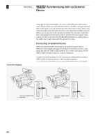
b Synchronizing with an External Recording 3 Device Using a Reference Video Signal (Genlock Synchronization) When a reference sync signal (analog blackburst or tri-level signal) is input through the GENLOCK terminal, the phases of the camcorder's V and H sync will automatically be synchronized to it. The phase difference between the external Genlock signal and the camcorder is initially set to 0. The H phase can be adjusted within the range of approximately ±0.4 H (HD equivalent). Operating modes: 1 Open the [Genlock] submenu. [J Other Functions] [Genlock] 2 Adjust the phase to the desired level and then press SET. Using a Time Code Signal An external SMPTE-standard LTC timing signal received from the TIME CODE terminal will be recorded as the time code. The user bit of the external timing signal can also be recorded. Before connecting the device, set the TIME CODE terminal to input. Also, you must set the running mode of the time code to [Free Run] (0 84). Operating modes: 1 Open the [TC In/Out] submenu. [L TC/UB Setup] [Time Code] 2 Select [In] and then press SET. [TC In/Out] Recording the User Bit of an External Signal The user bit of an external time code signal can also be recorded with the time code itself. 1 Open the user bit [Rec Mode] submenu. [L TC/UB Setup] [User Bit] [Rec Mode] 2 Select [External] and then press SET. NOTES • The Genlock signal synchronization stabilizes after approximately 10 seconds. • Genlock synchronization is possible even when a standard definition Genlock signal is input. However, Genlock synchronization is not possible when the camcorder's video configuration is 1080i and the input signal is 720P. [J Other Functions] [Genlock] [L TC/UB Setup] [Time Code] [TC In/Out] [In] [L TC/UB Setup] [User Bit] [Rec Mode] [Internal] 89
-
 1
1 -
2
-
3
-
4
-
5
-
6
-
7
-
8
-
9
-
10
-
11
-
12
-
13
-
14
-
15
-
16
-
17
-
18
-
19
-
20
-
21
-
22
-
23
-
24
-
25
-
26
-
27
-
28
-
29
-
30
-
31
-
32
-
33
-
34
-
35
-
36
-
37
-
38
-
39
-
40
-
41
-
42
-
43
-
44
-
45
-
46
-
47
-
48
-
49
-
50
-
51
-
52
-
53
-
54
-
55
-
56
-
57
-
58
-
59
-
60
-
61
-
62
-
63
-
64
-
65
-
66
-
67
-
68
-
69
-
70
-
71
-
72
-
73
-
74
-
75
-
76
-
77
-
78
-
79
-
80
-
81
-
82
-
83
-
 84
84 -
 85
85 -
 86
86 -
 87
87 -
 88
88 -
 89
89 -
 90
90 -
 91
91 -
 92
92 -
 93
93 -
 94
94 -
95
-
96
-
97
-
98
-
99
-
100
-
101
-
102
-
103
-
104
-
105
-
106
-
107
-
108
-
109
-
110
-
111
-
112
-
113
-
114
-
115
-
116
-
117
-
118
-
119
-
120
-
121
-
122
-
123
-
124
-
125
-
126
-
127
-
128
-
129
-
130
-
131
-
132
-
133
-
134
-
135
-
136
-
137
-
138
-
139
-
140
-
141
-
142
-
143
-
144
-
145
-
146
-
147
-
148
-
149
-
150
-
151
-
152
-
153
-
154
-
155
-
156
-
157
-
158
-
159
-
160
-
161
-
162
-
163
-
164
-
165
-
166
-
167
-
168
-
169
-
170
-
171
-
172
-
173
-
174
-
175
-
176
-
177
-
178
-
179
-
180
-
181
-
182
-
183
-
184
-
185
-
186
-
187
-
188
-
189
-
190
-
191
-
192
-
193
-
194
-
195
-
196
-
197
-
198
-
199
-
200
-
201
-
202
-
203
-
204
-
205
-
206
-
207
-
208
 |
 |
