Canon XF305 XF300 / XF305 Instruction Manual - Page 90
Time Code Signal Output
 |
View all Canon XF305 manuals
Add to My Manuals
Save this manual to your list of manuals |
Page 90 highlights
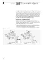
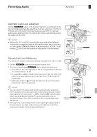
3 Recording b Synchronizing with an External Device • If the external Genlock signal is incorrect or there is no input signal, the external time code that is recorded may be incorrect. • While a time code signal is being received, the external time code's drop-frame bit will be used (if the external time code is non-drop frame, "NDF" will appear on the side panel). • When an external time code signal is received, the camcorder's own time code will be synchronized to it and the synchronization will be maintained even if you disconnect the cable from the TIME CODE terminal. However, performing any of the following actions while the cable is not connected will cause the synchronization to be disrupted; the correct time code will be restored once you reconnect the cable. - Turning the camcorder off/on - Changing the operating mode to mode - Changing the video configuration - Changing the frame rate • If the external time code signal is incorrect or there is no input signal, the internal time code set in the [L TC/UB Setup] [Time Code] submenu will be recorded instead. • When the camcorder locks on an external time code signal, [EXT-LOCK] appears on the side panel. Time Code Signal Output The time code will be output from the TIME CODE terminal as an SMPTEstandard LTC timing signal. The user bit will also be output. Before connecting the device, set the TIME CODE terminal to output. If you set the [N Video Setup] [SDI Output] setting to [HD] or [SD], the embedded time code will be output from the HD/SD SDI terminal. Operating modes: NOTES • The user bit of the time code signal is output while the camcorder is recording in mode or during playback of a clip in mode. When the [J Other Functions] [Frame Rate] setting is set to [24P] and the [L TC/UB Setup] [User Bit] [Output Mode] setting is set to [Pulldown], the user bit will be 2:3 pulldown data. In other words, when a recording in 24P mode is output from the HD/SD SDI terminal, the signal is converted to 60i using the 2:3 pulldown method. An external device can receive the data used in this conversion (2:3 pulldown data) to convert the signal to 1080/24P specifications. 90
-
 1
1 -
2
-
3
-
4
-
5
-
6
-
7
-
8
-
9
-
10
-
11
-
12
-
13
-
14
-
15
-
16
-
17
-
18
-
19
-
20
-
21
-
22
-
23
-
24
-
25
-
26
-
27
-
28
-
29
-
30
-
31
-
32
-
33
-
34
-
35
-
36
-
37
-
38
-
39
-
40
-
41
-
42
-
43
-
44
-
45
-
46
-
47
-
48
-
49
-
50
-
51
-
52
-
53
-
54
-
55
-
56
-
57
-
58
-
59
-
60
-
61
-
62
-
63
-
64
-
65
-
66
-
67
-
68
-
69
-
70
-
71
-
72
-
73
-
74
-
75
-
76
-
77
-
78
-
79
-
80
-
81
-
82
-
83
-
84
-
 85
85 -
 86
86 -
 87
87 -
 88
88 -
 89
89 -
 90
90 -
 91
91 -
 92
92 -
 93
93 -
 94
94 -
 95
95 -
96
-
97
-
98
-
99
-
100
-
101
-
102
-
103
-
104
-
105
-
106
-
107
-
108
-
109
-
110
-
111
-
112
-
113
-
114
-
115
-
116
-
117
-
118
-
119
-
120
-
121
-
122
-
123
-
124
-
125
-
126
-
127
-
128
-
129
-
130
-
131
-
132
-
133
-
134
-
135
-
136
-
137
-
138
-
139
-
140
-
141
-
142
-
143
-
144
-
145
-
146
-
147
-
148
-
149
-
150
-
151
-
152
-
153
-
154
-
155
-
156
-
157
-
158
-
159
-
160
-
161
-
162
-
163
-
164
-
165
-
166
-
167
-
168
-
169
-
170
-
171
-
172
-
173
-
174
-
175
-
176
-
177
-
178
-
179
-
180
-
181
-
182
-
183
-
184
-
185
-
186
-
187
-
188
-
189
-
190
-
191
-
192
-
193
-
194
-
195
-
196
-
197
-
198
-
199
-
200
-
201
-
202
-
203
-
204
-
205
-
206
-
207
-
208
 |
 |