Cisco 4948-10GE Installation Guide - Page 29
Switch Components, Traffic Ports on the Catalyst 4948, Console Port - s specifications
 |
UPC - 746320958668
View all Cisco 4948-10GE manuals
Add to My Manuals
Save this manual to your list of manuals |
Page 29 highlights
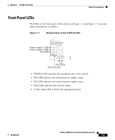
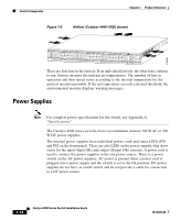
Chapter 1 Product Overview Switch Components Switch Components This section describes the hardware components. Traffic Ports on the Catalyst 4948 There are 48 10/100/1000BASE-T Ethernet ports using RJ-45 interfaces and four 1000BASE-X Ethernet ports using SFP interfaces. These SFP ports share MAC addresses with the last four 10/100/1000BASE-T ports. The interface configuration mode command media-type sfp | rj45 can be used to configure the media type for these ports in the switch software and to determine whether the SFP connector or the RJ-45 connector is used. The default is SFP. Traffic Ports on the Catalyst 4948-10GE There are 48 10/100/1000BASE-T Ethernet ports using RJ-45 interfaces and two 10-Gigabit Ethernet uplink ports using X2 interfaces. Traffic Ports on the Catalyst 4928-10GE There are 28 1000BASE-X Ethernet ports using SFP interfaces. Console Port A console serial port (RJ-45) provides for switch management using standard console equipment. (See Figure 1-4.) A connector pinout table is provided in Appendix A, "Specifications," for the console and management ports. The Management port on the front panel is only operational when the switch is in rommon mode. When in use, it offers the same TCP/IP based management services available using inband access (Telnet, SNMP, etc.). IP address configuration using BOOTP is supported on the Management port; it also supports image download to the switch. Figure 1-4 and Figure 1-5 show the location of the management and console ports on the switches. 78-18039-02 Catalyst 4900 Series Switch Installation Guide 1-7
-
 1
1 -
2
-
3
-
4
-
5
-
6
-
7
-
8
-
9
-
10
-
11
-
12
-
13
-
14
-
15
-
16
-
17
-
18
-
19
-
20
-
21
-
22
-
23
-
 24
24 -
 25
25 -
 26
26 -
 27
27 -
 28
28 -
 29
29 -
 30
30 -
 31
31 -
 32
32 -
 33
33 -
 34
34 -
35
-
36
-
37
-
38
-
39
-
40
-
41
-
42
-
43
-
44
-
45
-
46
-
47
-
48
-
49
-
50
-
51
-
52
-
53
-
54
-
55
-
56
-
57
-
58
-
59
-
60
-
61
-
62
-
63
-
64
-
65
-
66
-
67
-
68
-
69
-
70
-
71
-
72
-
73
-
74
-
75
-
76
-
77
-
78
-
79
-
80
-
81
-
82
-
83
-
84
-
85
-
86
-
87
-
88
-
89
-
90
-
91
-
92
-
93
-
94
-
95
-
96
-
97
-
98
-
99
-
100
-
101
-
102
-
103
-
104
-
105
-
106
-
107
-
108
-
109
-
110
-
111
-
112
-
113
-
114
-
115
-
116
-
117
-
118
-
119
-
120
-
121
-
122
-
123
-
124
-
125
-
126
-
127
-
128
-
129
-
130
-
131
-
132
-
133
-
134
-
135
-
136
-
137
-
138
-
139
-
140
-
141
-
142
 |
 |