Cisco 4948-10GE Installation Guide - Page 53
Attaching the L Brackets to the Switch, Table 3-1, Rack-Mount Kit Checklist, Step 2 - configuration
 |
UPC - 746320958668
View all Cisco 4948-10GE manuals
Add to My Manuals
Save this manual to your list of manuals |
Page 53 highlights
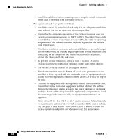
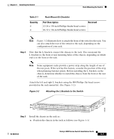
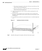
Chapter 3 Installing the Switch Rack-Mounting the Switch Table 3-1 Quantity 4 4 Rack-Mount Kit Checklist Part Description Received 12-24 x 3/4-inch Phillips binder-head screws 10-32 x 3/4-inch Phillips binder-head screws Note Figure 3-2 illustrates how to attach the front of the switch to the rack. You can also attach the rear of the switch to the rack, depending on the configuration of your rack. Step 2 Note that the L brackets connect the chassis to the rack. You can mount the L brackets to the front or rear mounting holes of the chassis, depending on which end is in the front of the rack. Note Some equipment racks provide a power strip along the length of one of the rear posts. If the rack has this feature, consider the position of the strip when planning fastener points. Before installing the L brackets on the chassis, determine whether to install the chassis from the front or the rear of the rack. Attach the left and right L brackets using the M4 Phillips flat-head screws provided in the rack-mount kit. (See Figure 3-2.) Figure 3-2 Attaching the L Brackets to the Switch 130086 PS1 PS2 FAN STATUS 1 16 17 32 33 Catalyst WS-C4948 10GE X2-1 X2-2 CON 48 MGT Step 3 Install the chassis in the rack as: a. Position the chassis in the rack as follows (see Figure 3-3): 78-18039-02 Catalyst 4900 Series Switch Installation Guide 3-7
-
 1
1 -
2
-
3
-
4
-
5
-
6
-
7
-
8
-
9
-
10
-
11
-
12
-
13
-
14
-
15
-
16
-
17
-
18
-
19
-
20
-
21
-
22
-
23
-
24
-
25
-
26
-
27
-
28
-
29
-
30
-
31
-
32
-
33
-
34
-
35
-
36
-
37
-
38
-
39
-
40
-
41
-
42
-
43
-
44
-
45
-
46
-
47
-
 48
48 -
 49
49 -
 50
50 -
 51
51 -
 52
52 -
 53
53 -
 54
54 -
 55
55 -
 56
56 -
 57
57 -
 58
58 -
59
-
60
-
61
-
62
-
63
-
64
-
65
-
66
-
67
-
68
-
69
-
70
-
71
-
72
-
73
-
74
-
75
-
76
-
77
-
78
-
79
-
80
-
81
-
82
-
83
-
84
-
85
-
86
-
87
-
88
-
89
-
90
-
91
-
92
-
93
-
94
-
95
-
96
-
97
-
98
-
99
-
100
-
101
-
102
-
103
-
104
-
105
-
106
-
107
-
108
-
109
-
110
-
111
-
112
-
113
-
114
-
115
-
116
-
117
-
118
-
119
-
120
-
121
-
122
-
123
-
124
-
125
-
126
-
127
-
128
-
129
-
130
-
131
-
132
-
133
-
134
-
135
-
136
-
137
-
138
-
139
-
140
-
141
-
142
 |
 |