Cisco 4948-10GE Installation Guide - Page 38
Site Power Requirements - specifications
 |
UPC - 746320958668
View all Cisco 4948-10GE manuals
Add to My Manuals
Save this manual to your list of manuals |
Page 38 highlights
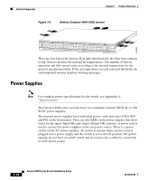
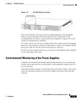
Site Power Requirements Chapter 2 Site Planning The switch operates as a standalone system mounted in a rack in a secure wiring closet. It requires a dry, clean, well-ventilated, and air-conditioned environment. To ensure normal operation, maintain ambient airflow. If the airflow is blocked or restricted, or if the intake air is too warm, an overtemperature condition can occur. The switch environmental monitor can then shut down the system to protect the system components. To ensure normal operation and avoid unnecessary maintenance, plan your site configuration and prepare your site before installation. After installation, make sure that the site maintains an ambient temperature of 0 to 40° C (32 to 104° F). It is essential to keep the area around the chassis as free from dust and foreign conductive material (such as metal flakes from nearby construction activity) as is possible. Multiple switches can be rack-mounted with little or no clearance above and below the chassis. However, when mounting a switch in a rack with other equipment, or when placing it on the floor near other equipment, ensure that the exhaust from other equipment does not blow into the intake vents of the chassis. Cooling air is drawn in through the sides and exhausted through the rear of the chassis. Keep the sides and rear clear of obstructions, including dust and foreign conductive material, and away from the exhaust ports of other equipment. Appendix A, "Specifications," lists the operating and nonoperating environmental site requirements for the switches. To maintain normal operation and ensure high system availability, maintain an ambient temperature and EMI-free and continuous power at your site. The environmental ranges listed in Appendix A are those within which the switch will continue to operate; however, a measurement that approaches the minimum or maximum of a range indicates a potential problem. You can maintain normal operation by anticipating and correcting environmental anomalies before they exceed the maximum operating range. Site Power Requirements This section describes the installation site power requirements for the switch. Verify your site power before you install the switch. This section consists of the following sections: • Pre-installation Requirements, page 2-3 • Warnings and Cautions, page 2-3 Catalyst 4900 Series Switch Installation Guide 2-2 78-18039-02
-
 1
1 -
2
-
3
-
4
-
5
-
6
-
7
-
8
-
9
-
10
-
11
-
12
-
13
-
14
-
15
-
16
-
17
-
18
-
19
-
20
-
21
-
22
-
23
-
24
-
25
-
26
-
27
-
28
-
29
-
30
-
31
-
32
-
 33
33 -
 34
34 -
 35
35 -
 36
36 -
 37
37 -
 38
38 -
 39
39 -
 40
40 -
 41
41 -
 42
42 -
 43
43 -
44
-
45
-
46
-
47
-
48
-
49
-
50
-
51
-
52
-
53
-
54
-
55
-
56
-
57
-
58
-
59
-
60
-
61
-
62
-
63
-
64
-
65
-
66
-
67
-
68
-
69
-
70
-
71
-
72
-
73
-
74
-
75
-
76
-
77
-
78
-
79
-
80
-
81
-
82
-
83
-
84
-
85
-
86
-
87
-
88
-
89
-
90
-
91
-
92
-
93
-
94
-
95
-
96
-
97
-
98
-
99
-
100
-
101
-
102
-
103
-
104
-
105
-
106
-
107
-
108
-
109
-
110
-
111
-
112
-
113
-
114
-
115
-
116
-
117
-
118
-
119
-
120
-
121
-
122
-
123
-
124
-
125
-
126
-
127
-
128
-
129
-
130
-
131
-
132
-
133
-
134
-
135
-
136
-
137
-
138
-
139
-
140
-
141
-
142
 |
 |
