Cisco 4948-10GE Installation Guide - Page 32
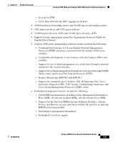
Color or State, Description, Table 1-1, LED Functions - 48 port
 |
UPC - 746320958668
View all Cisco 4948-10GE manuals
Add to My Manuals
Save this manual to your list of manuals |
Page 32 highlights
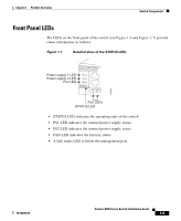
Switch Components Chapter 1 Product Overview Table 1-1 describes LED functions. Table 1-1 LED Functions LED STATUS Color or State Green Description At startup, the switch performs a series of diagnostic tests: All tests pass Red A test other than an individual port test fails Flashing System boot or diagnostic tests in progress Yellow System is in rommon mode or a power supply has failed CON MGT Port 1-48 Off Green Off Green Off Green Yellow Flashing yellow Off Switch is disabled 10/100 BASE-T console port is in link-up state 10/100 BASE-T console port is in link-down state or not connected There are no blinking, red, or yellow states for this port 10/100 BASE-T Management port is in link-up state 10/100 BASE-T Management port is in link-down state or not connected There are no blinking, red, or yellow states for this port Port is operational Port is disabled by user Power-on self-test indicates faulty port No signal detected or link configuration failure 1-10 Catalyst 4900 Series Switch Installation Guide 78-18039-02
-
 1
1 -
2
-
3
-
4
-
5
-
6
-
7
-
8
-
9
-
10
-
11
-
12
-
13
-
14
-
15
-
16
-
17
-
18
-
19
-
20
-
21
-
22
-
23
-
24
-
25
-
26
-
 27
27 -
 28
28 -
 29
29 -
 30
30 -
 31
31 -
 32
32 -
 33
33 -
 34
34 -
 35
35 -
 36
36 -
 37
37 -
38
-
39
-
40
-
41
-
42
-
43
-
44
-
45
-
46
-
47
-
48
-
49
-
50
-
51
-
52
-
53
-
54
-
55
-
56
-
57
-
58
-
59
-
60
-
61
-
62
-
63
-
64
-
65
-
66
-
67
-
68
-
69
-
70
-
71
-
72
-
73
-
74
-
75
-
76
-
77
-
78
-
79
-
80
-
81
-
82
-
83
-
84
-
85
-
86
-
87
-
88
-
89
-
90
-
91
-
92
-
93
-
94
-
95
-
96
-
97
-
98
-
99
-
100
-
101
-
102
-
103
-
104
-
105
-
106
-
107
-
108
-
109
-
110
-
111
-
112
-
113
-
114
-
115
-
116
-
117
-
118
-
119
-
120
-
121
-
122
-
123
-
124
-
125
-
126
-
127
-
128
-
129
-
130
-
131
-
132
-
133
-
134
-
135
-
136
-
137
-
138
-
139
-
140
-
141
-
142
 |
 |