Cisco 4948-10GE Installation Guide - Page 50
heat that is drawn upward and into the intake ports of equipment above - airflow
 |
UPC - 746320958668
View all Cisco 4948-10GE manuals
Add to My Manuals
Save this manual to your list of manuals |
Page 50 highlights
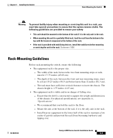
Rack-Mounting the Switch Chapter 3 Installing the Switch - Install the stabilizers before mounting or servicing the switch in the rack (if the rack is provided with stabilizing devices). • The equipment rack is properly ventilated. - Install the chassis in an enclosed rack only if it has adequate ventilation or an exhaust fan; use an open rack whenever possible. - Ensure that the ambient temperature of the rack environment does not exceed a maximum temperature of 104° F (40° C). Note that if the switch is installed in a closed or multiunit rack assembly, the ambient operating temperature of the rack environment might be higher than the ambient room temperature. - Note that a ventilation system in a closed rack that is too powerful might also prevent cooling by creating negative pressure around the chassis and redirecting the air away from the chassis intake vent. If necessary, operate the chassis with the rack open. - To prevent airflow restriction, allow at least 3 inches (7.6 cm) of clearance around the ventilation openings on the sides of the chassis. - Use baffles correctly to assist in cooling the chassis. - Note that equipment near the bottom of a rack may generate excessive heat that is drawn upward and into the intake ports of equipment above, leading to overtemperature conditions in the chassis at or near the top of the rack. - Consider the equipment and cabling that is already installed in the rack. Ensure that cables from other equipment will not obstruct the airflow through the chassis or impair access to the power supplies or switching modules. Route cables away from field-replaceable components to avoid disconnecting cables unnecessarily for equipment maintenance or upgrades. - Allow at least 3 to 4 feet (91.4 to 121.9 cm) of clearance behind the rack for maintenance and removal of switch assemblies. If the rack is mobile, you can push it back within 1 foot (30.45 cm) of a wall or cabinet for normal operation and pull it out when necessary for maintenance. Catalyst 4900 Series Switch Installation Guide 3-4 78-18039-02
-
 1
1 -
2
-
3
-
4
-
5
-
6
-
7
-
8
-
9
-
10
-
11
-
12
-
13
-
14
-
15
-
16
-
17
-
18
-
19
-
20
-
21
-
22
-
23
-
24
-
25
-
26
-
27
-
28
-
29
-
30
-
31
-
32
-
33
-
34
-
35
-
36
-
37
-
38
-
39
-
40
-
41
-
42
-
43
-
44
-
 45
45 -
 46
46 -
 47
47 -
 48
48 -
 49
49 -
 50
50 -
 51
51 -
 52
52 -
 53
53 -
 54
54 -
 55
55 -
56
-
57
-
58
-
59
-
60
-
61
-
62
-
63
-
64
-
65
-
66
-
67
-
68
-
69
-
70
-
71
-
72
-
73
-
74
-
75
-
76
-
77
-
78
-
79
-
80
-
81
-
82
-
83
-
84
-
85
-
86
-
87
-
88
-
89
-
90
-
91
-
92
-
93
-
94
-
95
-
96
-
97
-
98
-
99
-
100
-
101
-
102
-
103
-
104
-
105
-
106
-
107
-
108
-
109
-
110
-
111
-
112
-
113
-
114
-
115
-
116
-
117
-
118
-
119
-
120
-
121
-
122
-
123
-
124
-
125
-
126
-
127
-
128
-
129
-
130
-
131
-
132
-
133
-
134
-
135
-
136
-
137
-
138
-
139
-
140
-
141
-
142
 |
 |