Cisco 5508 Installation Guide - Page 13
Installing the Rear Bracket Adapters, Installing the Controller in the Rack Front, Step 2 - 12
 |
UPC - 882658250057
View all Cisco 5508 manuals
Add to My Manuals
Save this manual to your list of manuals |
Page 13 highlights
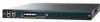
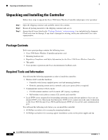
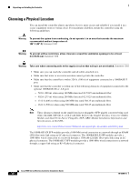
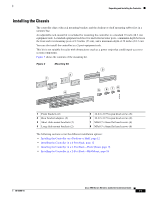
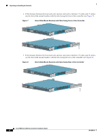
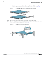
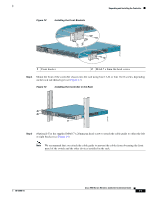
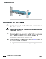
Unpacking and Installing the Controller Step 2 Attach one of the rear bracket adapters using three M3 screws (see Figure 5). Follow the same steps to attach the second bracket adapter to the opposite side. Figure 5 Installing the Rear Bracket Adapters RP SP USB0 USB1 CONSOLE EN EN Cisco 5500 Series Wireless Controller 12 34 56 78 Model 5508 PS1 PS2 SYS ACT 1 2 251201 1 Rear bracket adapter 2 M3x0.5 x 6mm flat head screws Step 3 Mount the front of the controller chassis into the rack using four 12-24 or four 10-32 screws, depending on the rack rail thread type (see Figure 6). Figure 6 Installing the Controller in the Rack (Front) RP SP USB0 USB1 CONSOLE EN EN Cisco 5500 Series Wireless Controller 12 34 56 78 Model 5508 PS1 PS2 SYS ACT 251202 Step 4 Measure the distance between the front and rear rack rails and select the proper slide-mount brackets: Note The slide-mount brackets allow you to mount the rear of the controller chassis to the rear rack rails. The brackets are designed to slide within the installed rear bracket adapters and accommodate a range of rack depths. 78-18998-01 Cisco 5500 Series Wireless Controller Installation Guide 13
-
 1
1 -
2
-
3
-
4
-
5
-
6
-
7
-
 8
8 -
 9
9 -
 10
10 -
 11
11 -
 12
12 -
 13
13 -
 14
14 -
 15
15 -
 16
16 -
 17
17 -
 18
18 -
19
-
20
-
21
-
22
-
23
-
24
-
25
-
26
-
27
-
28
-
29
-
30
-
31
-
32
-
33
-
34
 |
 |