Cisco 5508 Installation Guide - Page 27
Verifying Interface Settings and Port Operation, Connecting the Network (Distribution System - lag
 |
UPC - 882658250057
View all Cisco 5508 manuals
Add to My Manuals
Save this manual to your list of manuals |
Page 27 highlights
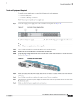
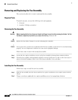
Using the Startup Wizard Verifying Interface Settings and Port Operation Follow these steps to verify that your interface configurations have been set properly and the controller's ports are operational. Step 1 Enter show interface summary. The controller's current interface configurations appear: Step 2 Interface Name management service-port virtual Port ---LAG N/A N/A Vlan Id -------untagged N/A N/A IP Address 10.91.104.93 10.10.0.9 1.1.1.1 Type ------Static Static Static Ap Mgr Guest Yes No No No No No Enter show port summary. The following information appears, showing the status of the controller's distribution system ports, which serve as the data path between the controller and Cisco lightweight access points and to which the controller's management interface is mapped. STP Admin Physical Physical Link Link Mcast Pr Type Stat Mode Mode Status Status Trap Appliance POE 1 Normal Forw Enable Auto 1000 Full Up Enable Enable N/A 2 Normal Forw Enable Auto 1000 Full Up Enable Enable N/A A link status of Up indicates that the controller's ports are fully operational. Connecting the Network (Distribution System) Up to eight of the following SFP modules can be installed in any combination: • GLC-SX-MM (1000BASE-SX) SFP modules that provide a 1000 Mb/s wired connection to a network through an 850nM (SX) fiber-optic link using an LC physical connector. • GLC-LH-SM (1000BASE-LX) SFP modules that provide a 1000 Mb/s wired connection to a network through a 1300nM (LX/LH) fiber-optic link using an LC physical connector. • SFP-GE-T (1000BASE-T) SFP modules that provide a 1000 Mb/s wired connection to a network through a copper link using an RJ-45 physical connector. Depending on the distribution system physical port to be assigned, use Ethernet Category 5 or higher cables or SX/LX/LH compatible fiber-optic cables to connect the network equipment to the controller. 78-18998-01 Cisco 5500 Series Wireless Controller Installation Guide 27
-
 1
1 -
2
-
3
-
4
-
5
-
6
-
7
-
8
-
9
-
10
-
11
-
12
-
13
-
14
-
15
-
16
-
17
-
18
-
19
-
20
-
21
-
 22
22 -
 23
23 -
 24
24 -
 25
25 -
 26
26 -
 27
27 -
 28
28 -
 29
29 -
 30
30 -
 31
31 -
 32
32 -
33
-
34
 |
 |