Cisco 5508 Installation Guide - Page 28
Connecting the Switch’s Service Port (Optional), Connecting Access Points, Installing a Power Supply - gui
 |
UPC - 882658250057
View all Cisco 5508 manuals
Add to My Manuals
Save this manual to your list of manuals |
Page 28 highlights
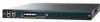
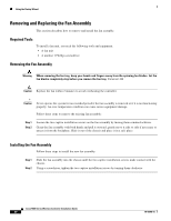
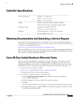
Using the Startup Wizard Connecting the Switch's Service Port (Optional) The service port is controlled by the service-port interface and is reserved for out-of-band management of the controller and system recovery and maintenance in the event of a network failure. The service-port interface enables the controller to be managed on an interface different from the one used for your network traffic. Use of the service port is optional. You can perform out-of-band controller management from a PC running a terminal emulation program or a PC running Cisco WCS, a network management tool that enables you to configure and monitor a network of controllers, or the controller GUI. However, you must first connect the PC to the switch's service port in one of two ways: • Use an Ethernet cross-over cable to connect the PC directly to the switch's service port. • For a remote connection (using Telnet or SSH) through a dedicated management network, use a Category 5, Category 5e, Category 6, or Category 7 Ethernet cable to connect the management network to the switch's service port and the appropriate cable to connect the PC to the management network. Connecting Access Points After you have configured the controller, use Category-5, Category-5e, Category-6, or Category-7 Ethernet cables to connect Cisco lightweight access points to the network. As soon as the controller is operational, it starts to scan for access points. When it detects an access point, it records the access-point MAC address in its database. The controller radio resource management (RRM) feature then automatically configures the access point to start sending and allowing clients to associate. You have prepared the controller for basic operation. Refer to the Cisco Wireless LAN Controller Configuration Guide, Release 6.0, for information on configuring the controller to meet the specific needs of your wireless network. Installing a Power Supply Unit The controller can be powered using one or two power supply units. When the controller is equipped with two power supply units, the power supplies are redundant. Either power supply continues to power the controller should the other power supply unit fail. Also, the power supplies are hot swappable; you do not need to remove power from the controller to replace a power supply. Note Before you remove or install a power supply, you must switch off and unplug the power supply. One power supply unit is installed in slot 1 at the factory. You can order a second power supply unit and install it in slot 2. Note If only one power supply will be used, you must use the supplied blank faceplate to cover the empty power slot. Cisco 5500 Series Wireless Controller Installation Guide 28 78-18998-01
-
 1
1 -
2
-
3
-
4
-
5
-
6
-
7
-
8
-
9
-
10
-
11
-
12
-
13
-
14
-
15
-
16
-
17
-
18
-
19
-
20
-
21
-
22
-
 23
23 -
 24
24 -
 25
25 -
 26
26 -
 27
27 -
 28
28 -
 29
29 -
 30
30 -
 31
31 -
 32
32 -
 33
33 -
34
 |
 |