Cisco 5508 Installation Guide - Page 22
Connecting the Controller’s Console Port, Running the Bootup Script and Power-On Self Test - configuration
 |
UPC - 882658250057
View all Cisco 5508 manuals
Add to My Manuals
Save this manual to your list of manuals |
Page 22 highlights
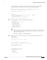
Unpacking and Installing the Controller Connecting the Controller's Console Port Before you can configure the controller for basic operations, you need to connect it to a PC that uses a VT-100 terminal emulator (such as HyperTerminal, ProComm, Minicom, or Tip). Note You can use either the RJ-45 console port or the USB console port (see Figure 1). Note The first time that you connect a Windows PC to the USB console port, you are prompted to install the USB console driver. Follow the installation prompts to install the driver. The USB console driver maps to a COM port on your PC; you then need to map the terminal emulator application to the COM port. See the "USB Console" section on page 4 for more information about the USB console driver. Follow these steps to connect the PC to the controller's console port: Step 1 Step 2 Step 3 If you use the RJ-45 console port, plug the RJ-45 connector on a null-modem serial cable into the controller's RJ-45 console port and the other end of the cable into the PC's serial port. If you use the USB console port, plug the 5-pin mini Type B connector into the controller's USB console port and the other end of the cable into the PC's USB Type A port. Start the PC's terminal emulation program. Configure the terminal emulation program for the following parameters: • 9600 baud • 8 data bits • No flow control • 1 stop bit • No parity Running the Bootup Script and Power-On Self Test When you plug the controller into an AC power source, the bootup script initializes the system, verifies the hardware configuration, loads its microcode into memory, verifies its operating system software load, and initializes itself with its stored configurations. Before performing this test, you should connect your PC to the controller's CLI console as described in the "Connecting the Controller's Console Port" section on page 22. Follow these steps to run the bootup script and conduct the power-on self test (POST). Step 1 Step 2 Step 3 Plug an AC power cord into the back of the controller and connect the other end to a grounded 100 to 240 VAC, 50/60 Hz electrical outlet. Turn on the power supply. Observe the bootup on the CLI screen. Cisco 5500 Series Wireless Controller Installation Guide 22 78-18998-01
-
 1
1 -
2
-
3
-
4
-
5
-
6
-
7
-
8
-
9
-
10
-
11
-
12
-
13
-
14
-
15
-
16
-
 17
17 -
 18
18 -
 19
19 -
 20
20 -
 21
21 -
 22
22 -
 23
23 -
 24
24 -
 25
25 -
 26
26 -
 27
27 -
28
-
29
-
30
-
31
-
32
-
33
-
34
 |
 |