Cisco 5508 Installation Guide - Page 4
Console Port Connections, EIA/TIA-232, USB Console - controller
 |
UPC - 882658250057
View all Cisco 5508 manuals
Add to My Manuals
Save this manual to your list of manuals |
Page 4 highlights
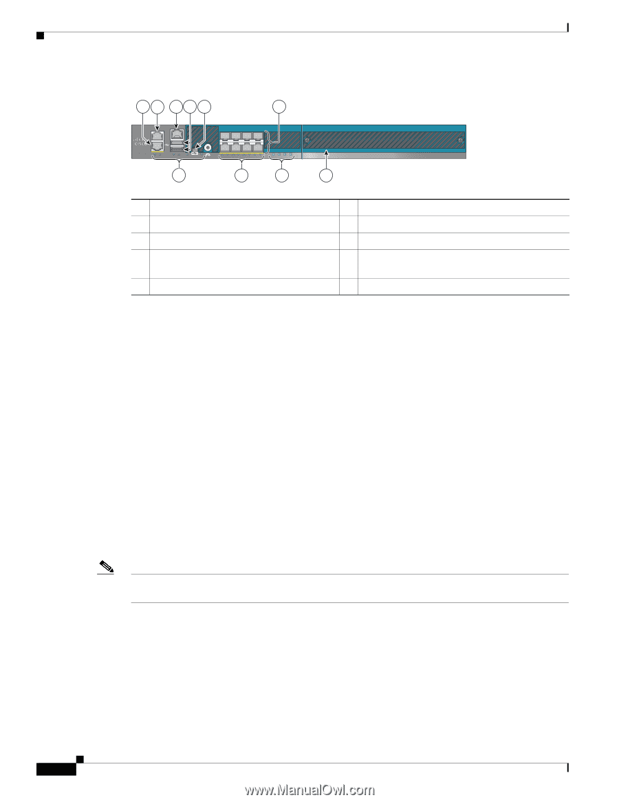
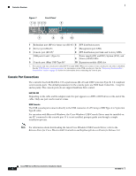
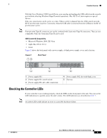
Controller Overview Figure 1 Front Panel 12 345 6 Cisco 5500 Series Wireless Controller RP SP USB0 USB1 EN EN 7 12 3 4 56 7 8 Model 5508 PS1 PS2 SYS ALM 8 9 10 251197 1 Redundant port (RP) for future use (RJ-45) 6 SFP distribution ports 2 Service port (RJ-45) 3 Console port (RJ-45)1 7 Management port LEDs 8 SFP distribution port Link and Activity LEDs USB ports 0 and 1 (Type A) 4 5 Console port (Mini USB Type B)1 Power supply (PS1 and PS2), System (SYS), and 9 Alarm (ALM) LEDs 10 Expansion module (EM) slot 1. You can use only one console port (either RJ-45 or mini-USB). When you connect to one console port, the other is disabled. See the "USB Console" section on page 4 for information on the USB console port. See the "Connecting the Controller's Console Port" section on page 22 section for information about connecting the console port. Console Port Connections The controller has both EIA/TIA-232 asynchronous (RJ-45) and USB 5-pin mini Type B, 2.0 compliant serial console ports. The default parameters for the console ports are 9600 baud, 8 data bits, 1 stop bit, and no parity. The console ports do not support hardware flow control. EIA/TIA-232 Depending on the cable and the adapter used, this port appears as a DTE or DCE device at the end of the cable. Only one port can be used at a time. USB Console The USB console port connects directly to the USB connector of a PC using a USB Type A to 5-pin mini Type B cable. For operation with Microsoft Windows, the Cisco Windows USB Console Driver must be installed on any PC connected to the console port. If it is not installed, prompts guide you through a simple installation process. Note For information about downloading the latest Cisco Windows USB Console Driver, refer to the Release Notes for Cisco Wireless LAN Controllers and Lightweight Access Points for Release 6.0. Cisco 5500 Series Wireless Controller Installation Guide 4 78-18998-01
-
 1
1 -
 2
2 -
 3
3 -
 4
4 -
 5
5 -
 6
6 -
 7
7 -
 8
8 -
 9
9 -
 10
10 -
11
-
12
-
13
-
14
-
15
-
16
-
17
-
18
-
19
-
20
-
21
-
22
-
23
-
24
-
25
-
26
-
27
-
28
-
29
-
30
-
31
-
32
-
33
-
34
 |
 |