Cisco 5508 Installation Guide - Page 25
Step 8, To con a RADIUS server now, enter - wireless controller configuration guide
 |
UPC - 882658250057
View all Cisco 5508 manuals
Add to My Manuals
Save this manual to your list of manuals |
Page 25 highlights
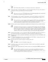
Using the Startup Wizard Note The VLAN identifier should be set to match the switch interface configuration. Step 8 Enter the IP address of the default DHCP server that will supply IP addresses to clients, the controller's management interface, and optionally the service-port interface. Note The management interface is the default interface for in-band management of the controller and connectivity to enterprise services such as AAA servers. Step 9 Enter the IP address of the controller's virtual interface, which will be used by all controller Layer 3 security and mobility managers. You should enter a fictitious, unassigned IP address, such as 1.1.1.1. Note The virtual interface is used to support mobility management, DHCP relay, and embedded Layer 3 security such as guest web authentication and VPN termination. All controllers within a mobility group must be configured with the same virtual interface IP address. Step 10 If desired, enter the name of the mobility group/RF group to which you want the controller to belong. Note Although the name that you enter here is assigned to both the mobility group and the RF group, these groups are not identical. Both groups define clusters of controllers, but they have different purposes. All of the controllers in an RF group are usually also in the same mobility group and vice versa. However, a mobility group facilitates scalable, system-wide mobility and controller redundancy while an RF group facilitates scalable, system-wide dynamic RF management. Step 11 Step 12 Step 13 Step 14 Enter the network name, or service set identifier (SSID). The initial SSID enables basic functionality of the controller and allows access points that have joined the controller to enable their radios. Enter yes to allow clients to assign their own IP address or no to make clients request an IP address from a DHCP server. To configure a RADIUS server now, enter yes and then enter the IP address, communication port, and secret key of the RADIUS server. Otherwise, enter no. Enter the code for the country in which the controller will be used. Note Enter help to view the list of available country codes. Step 15 Step 16 Enter yes to enable or no to disable each of the 802.11b, 802.11a, 802.11g, and 802.11n lightweight access point networks. Enter yes to enable or no to disable the controller's radio resource management (RRM) auto RF feature. Note The auto RF feature enables the controller to automatically form an RF group with other controllers. The group dynamically elects a leader to optimize RRM parameter settings, such as channel and transmit power assignment, for the group. 78-18998-01 Cisco 5500 Series Wireless Controller Installation Guide 25
-
 1
1 -
2
-
3
-
4
-
5
-
6
-
7
-
8
-
9
-
10
-
11
-
12
-
13
-
14
-
15
-
16
-
17
-
18
-
19
-
 20
20 -
 21
21 -
 22
22 -
 23
23 -
 24
24 -
 25
25 -
 26
26 -
 27
27 -
 28
28 -
 29
29 -
 30
30 -
31
-
32
-
33
-
34
 |
 |