Compaq 435 Maintenance and Service Guide - Page 63
Remove the keyboard., Reverse this procedure to install the keyboard.
 |
View all Compaq 435 manuals
Add to My Manuals
Save this manual to your list of manuals |
Page 63 highlights
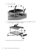
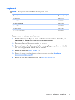
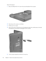
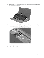
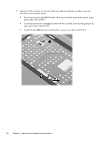
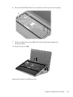
6. Lift the rear edge of the keyboard (1), and then swing the keyboard up and forward (2) until it rests upside down on the palm rest. 7. Release the zero insertion force (ZIF) connector (1) to which the keyboard cable is attached, and then disconnect the keyboard cable (2) from the system board. 8. Remove the keyboard. Reverse this procedure to install the keyboard. Component replacement procedures 55
-
 1
1 -
2
-
3
-
4
-
5
-
6
-
7
-
8
-
9
-
10
-
11
-
12
-
13
-
14
-
15
-
16
-
17
-
18
-
19
-
20
-
21
-
22
-
23
-
24
-
25
-
26
-
27
-
28
-
29
-
30
-
31
-
32
-
33
-
34
-
35
-
36
-
37
-
38
-
39
-
40
-
41
-
42
-
43
-
44
-
45
-
46
-
47
-
48
-
49
-
50
-
51
-
52
-
53
-
54
-
55
-
56
-
57
-
 58
58 -
 59
59 -
 60
60 -
 61
61 -
 62
62 -
 63
63 -
 64
64 -
 65
65 -
 66
66 -
 67
67 -
 68
68 -
69
-
70
-
71
-
72
-
73
-
74
-
75
-
76
-
77
-
78
-
79
-
80
-
81
-
82
-
83
-
84
-
85
-
86
-
87
-
88
-
89
-
90
-
91
-
92
-
93
-
94
-
95
-
96
-
97
-
98
-
99
-
100
-
101
-
102
-
103
-
104
-
105
-
106
-
107
-
108
-
109
-
110
-
111
-
112
-
113
-
114
-
115
-
116
-
117
-
118
-
119
-
120
-
121
-
122
-
123
-
124
-
125
 |
 |

6.
Lift the rear edge of the keyboard
(1)
, and then swing the keyboard up and forward
(2)
until it
rests upside down on the palm rest.
7.
Release the zero insertion force (ZIF) connector
(1)
to which the keyboard cable is attached, and
then disconnect the keyboard cable
(2)
from the system board.
8.
Remove the keyboard.
Reverse this procedure to install the keyboard.
Component replacement procedures
55