Compaq 435 Maintenance and Service Guide - Page 85
Remove the Phillips PM2.5×6.0 screw
 |
View all Compaq 435 manuals
Add to My Manuals
Save this manual to your list of manuals |
Page 85 highlights
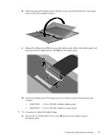
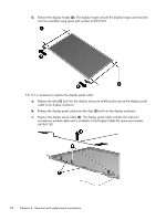
● USB board (see USB board on page 65) ● Power connector cable (see Power connector cable on page 66) ● Display assembly (see Display assembly on page 68) NOTE: When replacing the system board, be sure that the following components are removed from the defective system board and installed on the replacement system board: ● Memory module (see Memory module on page 47) ● RTC battery (see RTC battery on page 81) ● Fan/heat sink assembly (see Fan/heat sink assembly on page 83) ● Processor (see Processor on page 89) Remove the system board: 1. Disconnect the optical drive connector cable from the system board. 2. Remove the Phillips PM2.5×6.0 screw (1) that secures the system board to the base enclosure. 3. Lift the right side of the system board (2) until it rests at an angle. Component replacement procedures 77
-
 1
1 -
2
-
3
-
4
-
5
-
6
-
7
-
8
-
9
-
10
-
11
-
12
-
13
-
14
-
15
-
16
-
17
-
18
-
19
-
20
-
21
-
22
-
23
-
24
-
25
-
26
-
27
-
28
-
29
-
30
-
31
-
32
-
33
-
34
-
35
-
36
-
37
-
38
-
39
-
40
-
41
-
42
-
43
-
44
-
45
-
46
-
47
-
48
-
49
-
50
-
51
-
52
-
53
-
54
-
55
-
56
-
57
-
58
-
59
-
60
-
61
-
62
-
63
-
64
-
65
-
66
-
67
-
68
-
69
-
70
-
71
-
72
-
73
-
74
-
75
-
76
-
77
-
78
-
79
-
 80
80 -
 81
81 -
 82
82 -
 83
83 -
 84
84 -
 85
85 -
 86
86 -
 87
87 -
 88
88 -
 89
89 -
 90
90 -
91
-
92
-
93
-
94
-
95
-
96
-
97
-
98
-
99
-
100
-
101
-
102
-
103
-
104
-
105
-
106
-
107
-
108
-
109
-
110
-
111
-
112
-
113
-
114
-
115
-
116
-
117
-
118
-
119
-
120
-
121
-
122
-
123
-
124
-
125
 |
 |
