Compaq 435 Maintenance and Service Guide - Page 77
Support the display assembly when removing the following screws. Failure
 |
View all Compaq 435 manuals
Add to My Manuals
Save this manual to your list of manuals |
Page 77 highlights
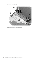
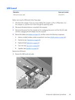
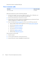
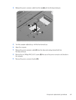
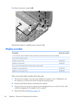
5. Disconnect the WLAN module antenna cables from the WLAN module (see WLAN module on page 44). 6. Remove the following components: ● Hard drive (see Hard drive on page 48) ● Keyboard (see Keyboard on page 53) ● Top cover (see Top cover on page 56) ● Speakers (see Speakers on page 63) ● USB board (see USB board on page 65) ● Power connector cable (see Power connector cable on page 66) Remove the display assembly: 1. Disconnect the display panel cable (1) from the system board. 2. Release the wireless antenna cables from the clips (2) built into the base enclosure. CAUTION: Support the display assembly when removing the following screws. Failure to support the display assembly can result in damage to the display assembly and other computer components. 3. Remove the four Phillips PM2.5×6.0 screws (3) that secure the display assembly to the computer. 4. Remove the display assembly (4). Component replacement procedures 69
-
 1
1 -
2
-
3
-
4
-
5
-
6
-
7
-
8
-
9
-
10
-
11
-
12
-
13
-
14
-
15
-
16
-
17
-
18
-
19
-
20
-
21
-
22
-
23
-
24
-
25
-
26
-
27
-
28
-
29
-
30
-
31
-
32
-
33
-
34
-
35
-
36
-
37
-
38
-
39
-
40
-
41
-
42
-
43
-
44
-
45
-
46
-
47
-
48
-
49
-
50
-
51
-
52
-
53
-
54
-
55
-
56
-
57
-
58
-
59
-
60
-
61
-
62
-
63
-
64
-
65
-
66
-
67
-
68
-
69
-
70
-
71
-
 72
72 -
 73
73 -
 74
74 -
 75
75 -
 76
76 -
 77
77 -
 78
78 -
 79
79 -
 80
80 -
 81
81 -
 82
82 -
83
-
84
-
85
-
86
-
87
-
88
-
89
-
90
-
91
-
92
-
93
-
94
-
95
-
96
-
97
-
98
-
99
-
100
-
101
-
102
-
103
-
104
-
105
-
106
-
107
-
108
-
109
-
110
-
111
-
112
-
113
-
114
-
115
-
116
-
117
-
118
-
119
-
120
-
121
-
122
-
123
-
124
-
125
 |
 |
