Compaq Evo n160 Maintenance and Service Guide Compaq Evo N160 Series - Page 78
Switch Cover
 |
View all Compaq Evo n160 manuals
Add to My Manuals
Save this manual to your list of manuals |
Page 78 highlights
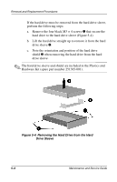
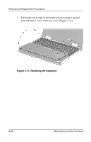
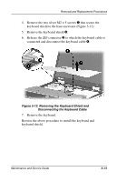
Removal and Replacement Procedures 5.6 Switch Cover ✎ The switch cover is included in the Plastics and Hardware Kit (spare part number 251365-001). 1. Prepare the computer for disassembly (Section 5.3). 2. Turn the computer bottom side up with the rear panel facing you. 3. Remove the two black M2 × 9 screws (Figure 5-9). Figure 5-9. Removing the Switch Cover Screws 4. Turn the computer top side up with the front facing you. 5. Open the computer as far as it will open. Maintenance and Service Guide 5-11
-
 1
1 -
2
-
3
-
4
-
5
-
6
-
7
-
8
-
9
-
10
-
11
-
12
-
13
-
14
-
15
-
16
-
17
-
18
-
19
-
20
-
21
-
22
-
23
-
24
-
25
-
26
-
27
-
28
-
29
-
30
-
31
-
32
-
33
-
34
-
35
-
36
-
37
-
38
-
39
-
40
-
41
-
42
-
43
-
44
-
45
-
46
-
47
-
48
-
49
-
50
-
51
-
52
-
53
-
54
-
55
-
56
-
57
-
58
-
59
-
60
-
61
-
62
-
63
-
64
-
65
-
66
-
67
-
68
-
69
-
70
-
71
-
72
-
 73
73 -
 74
74 -
 75
75 -
 76
76 -
 77
77 -
 78
78 -
 79
79 -
 80
80 -
 81
81 -
 82
82 -
 83
83 -
84
-
85
-
86
-
87
-
88
-
89
-
90
-
91
-
92
-
93
-
94
-
95
-
96
-
97
-
98
-
99
-
100
-
101
-
102
-
103
-
104
-
105
-
106
-
107
-
108
-
109
-
110
-
111
-
112
-
113
-
114
-
115
-
116
-
117
-
118
-
119
-
120
-
121
-
122
-
123
-
124
-
125
-
126
-
127
-
128
-
129
-
130
-
131
-
132
-
133
-
134
-
135
-
136
-
137
-
138
-
139
-
140
-
141
-
142
-
143
-
144
-
145
-
146
-
147
-
148
-
149
-
150
-
151
-
152
-
153
-
154
-
155
-
156
-
157
 |
 |
Removal and Replacement Procedures
Maintenance and Service Guide
5
–
11
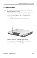
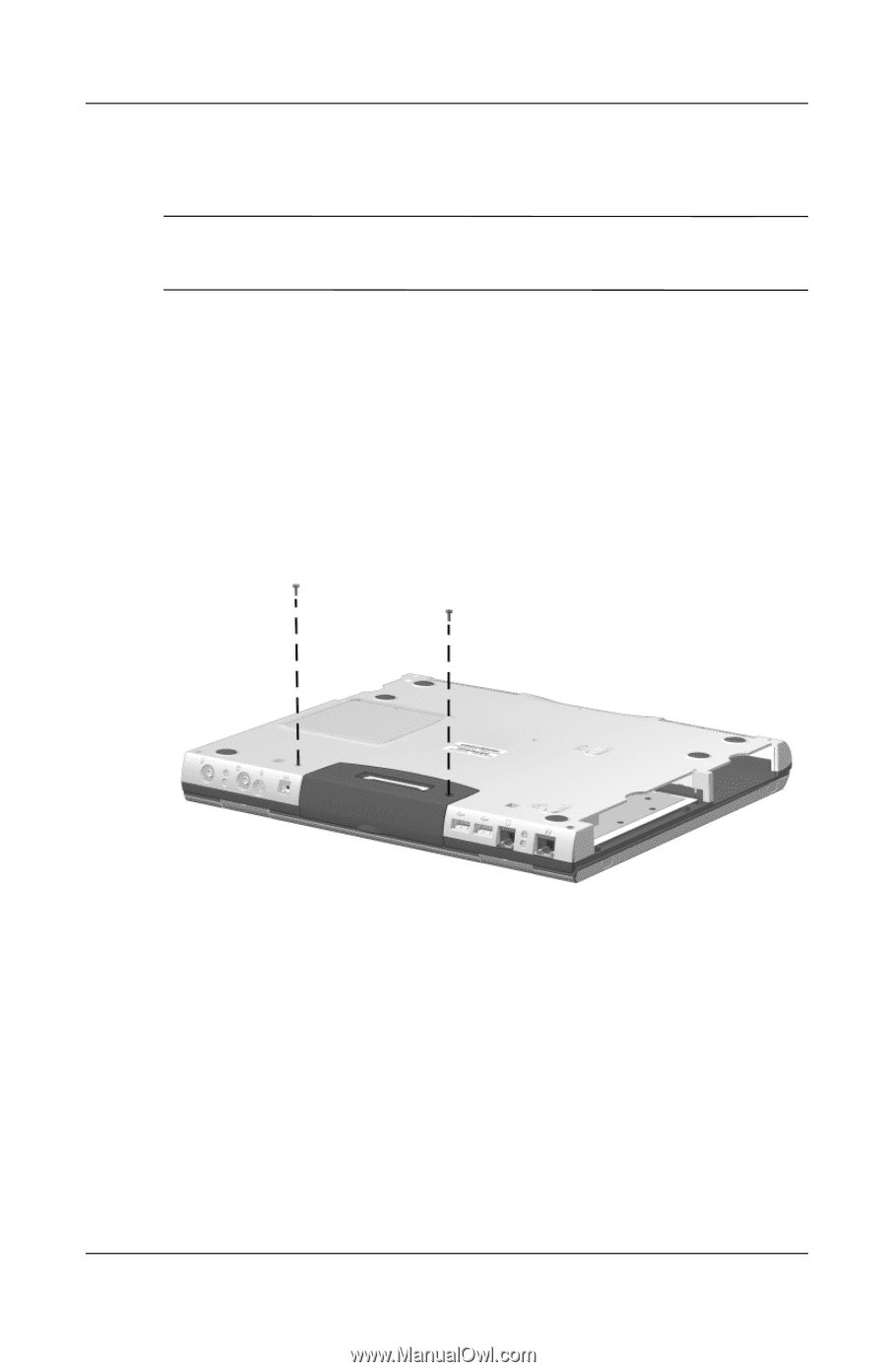
5.6 Switch Cover
✎
The switch cover is included in the Plastics and Hardware Kit
(spare part number 251365-001).
1.
Prepare the computer for disassembly (Section 5.3).
2.
Turn the computer bottom side up with the rear panel
facing you.
3.
Remove the two black M2
×
9 screws (Figure 5-9).
Figure 5-9. Removing the Switch Cover Screws
4.
Turn the computer top side up with the front facing you.
5.
Open the computer as far as it will open.