Compaq Evo n160 Maintenance and Service Guide Compaq Evo N160 Series - Page 89
Disconnecting the Display Cables,
 |
View all Compaq Evo n160 manuals
Add to My Manuals
Save this manual to your list of manuals |
Page 89 highlights
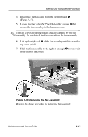
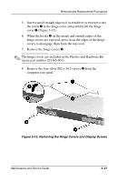
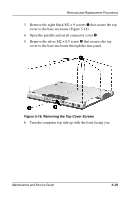
Removal and Replacement Procedures 9. Position the computer so the front faces you. 10. Open the computer as far as it will open. 11. Lift up the back edge of the keyboard and swing it forward until it rests on the top cover. 12. Disconnect the display inverter 1 and video cables 2 (Figure 5-16). ✎ When installing the display, route the display video cable through the clip 3 in the top cover. Figure 5-16. Disconnecting the Display Cables 5-22 Maintenance and Service Guide
-
 1
1 -
2
-
3
-
4
-
5
-
6
-
7
-
8
-
9
-
10
-
11
-
12
-
13
-
14
-
15
-
16
-
17
-
18
-
19
-
20
-
21
-
22
-
23
-
24
-
25
-
26
-
27
-
28
-
29
-
30
-
31
-
32
-
33
-
34
-
35
-
36
-
37
-
38
-
39
-
40
-
41
-
42
-
43
-
44
-
45
-
46
-
47
-
48
-
49
-
50
-
51
-
52
-
53
-
54
-
55
-
56
-
57
-
58
-
59
-
60
-
61
-
62
-
63
-
64
-
65
-
66
-
67
-
68
-
69
-
70
-
71
-
72
-
73
-
74
-
75
-
76
-
77
-
78
-
79
-
80
-
81
-
82
-
83
-
 84
84 -
 85
85 -
 86
86 -
 87
87 -
 88
88 -
 89
89 -
 90
90 -
 91
91 -
 92
92 -
 93
93 -
 94
94 -
95
-
96
-
97
-
98
-
99
-
100
-
101
-
102
-
103
-
104
-
105
-
106
-
107
-
108
-
109
-
110
-
111
-
112
-
113
-
114
-
115
-
116
-
117
-
118
-
119
-
120
-
121
-
122
-
123
-
124
-
125
-
126
-
127
-
128
-
129
-
130
-
131
-
132
-
133
-
134
-
135
-
136
-
137
-
138
-
139
-
140
-
141
-
142
-
143
-
144
-
145
-
146
-
147
-
148
-
149
-
150
-
151
-
152
-
153
-
154
-
155
-
156
-
157
 |
 |

5
–
22
Maintenance and Service Guide
Removal and Replacement Procedures
9.
Position the computer so the front faces you.
10.
Open the computer as far as it will open.
11.
Lift up the back edge of the keyboard and swing it forward
until it rests on the top cover.
12.
Disconnect the display inverter
1
and video cables
2
(Figure 5-16).
✎
When installing the display, route the display video cable through
the clip
3
in the top cover.
Figure 5-16. Disconnecting the Display Cables