Compaq Pro 4300 Maintenance & Service Guide Pro 4300 All-in-One Business P - Page 59
Heat Sink Cover
 |
View all Compaq Pro 4300 manuals
Add to My Manuals
Save this manual to your list of manuals |
Page 59 highlights
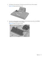
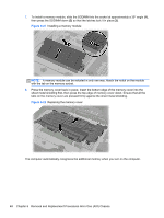
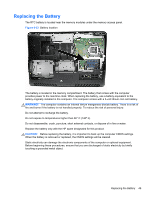
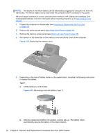
Heat Sink Cover The heat sink cover protects the heat sink and system board. It is secured with five Torx screws. Figure 6-28 Heat sink cover location To remove the heat sink cover: 1. Prepare the computer for disassembly (see Preparing to Disassemble the Computer on page 33). 2. Remove the center access panel (see Hinge Cover Panel on page 34). 3. Remove the memory access panel (see Memory Access Panel on page 36). 4. Remove the five black Torx screws that secure the cover to the computer. Figure 6-29 Heat sink cover screws 52 Chapter 6 Removal and Replacement Procedures All-in One (AIO) Chassis
-
 1
1 -
2
-
3
-
4
-
5
-
6
-
7
-
8
-
9
-
10
-
11
-
12
-
13
-
14
-
15
-
16
-
17
-
18
-
19
-
20
-
21
-
22
-
23
-
24
-
25
-
26
-
27
-
28
-
29
-
30
-
31
-
32
-
33
-
34
-
35
-
36
-
37
-
38
-
39
-
40
-
41
-
42
-
43
-
44
-
45
-
46
-
47
-
48
-
49
-
50
-
51
-
52
-
53
-
 54
54 -
 55
55 -
 56
56 -
 57
57 -
 58
58 -
 59
59 -
 60
60 -
 61
61 -
 62
62 -
 63
63 -
 64
64 -
65
-
66
-
67
-
68
-
69
-
70
-
71
-
72
-
73
-
74
-
75
-
76
-
77
-
78
-
79
-
80
-
81
-
82
-
83
-
84
-
85
-
86
-
87
-
88
-
89
-
90
-
91
-
92
-
93
-
94
-
95
-
96
-
97
-
98
-
99
-
100
-
101
-
102
-
103
-
104
-
105
-
106
-
107
-
108
-
109
-
110
-
111
-
112
-
113
-
114
-
115
-
116
-
117
-
118
-
119
-
120
-
121
-
122
-
123
-
124
-
125
-
126
-
127
-
128
-
129
-
130
-
131
-
132
-
133
-
134
-
135
-
136
-
137
-
138
-
139
-
140
-
141
-
142
-
143
-
144
-
145
-
146
-
147
-
148
-
149
-
150
-
151
-
152
-
153
-
154
-
155
-
156
-
157
-
158
-
159
-
160
-
161
-
162
 |
 |

Heat Sink Cover
The heat sink cover protects the heat sink and system board. It is secured with five Torx screws.
Figure 6-28
Heat sink cover location
To remove the heat sink cover:
1.
Prepare the computer for disassembly (see
Preparing to Disassemble the Computer
on page
33
).
2.
Remove the center access panel (see
Hinge Cover Panel
on page
34
).
3.
Remove the memory access panel (see
Memory Access Panel
on page
36
).
4.
Remove the five black Torx screws that secure the cover to the computer.
Figure 6-29
Heat sink cover screws
52
Chapter 6
Removal and Replacement Procedures All-in One (AIO) Chassis