Compaq dc7100 HP Compaq dc71xx and dx61xx Series Business Desktop Computers Te - Page 117
AC97 Audio Controller, 8.2 AC97 Link Bus
 |
View all Compaq dc7100 manuals
Add to My Manuals
Save this manual to your list of manuals |
Page 117 highlights
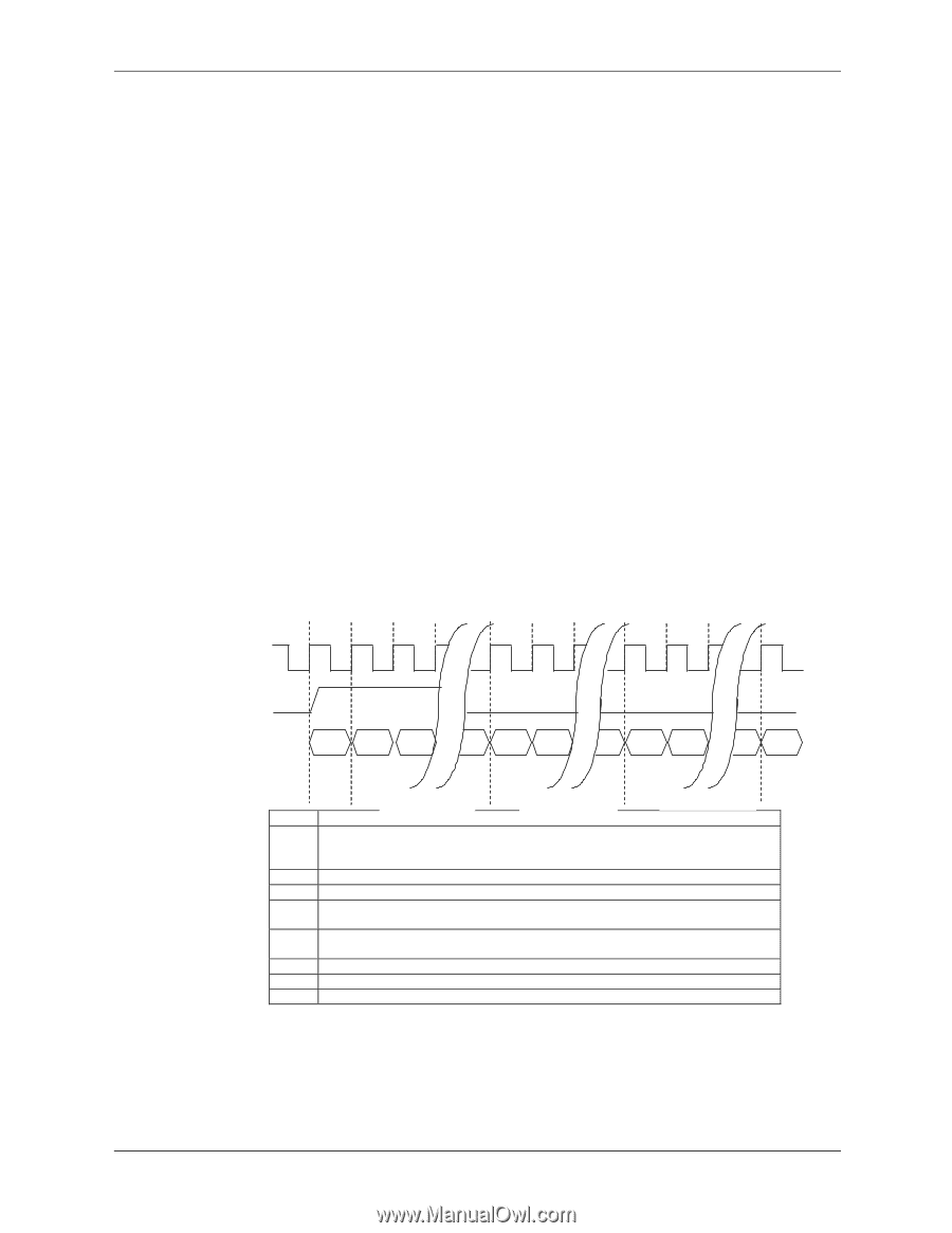
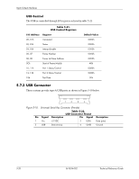
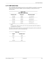
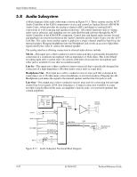
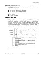
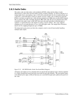
Input/Output Interfaces 5.8.1 AC97 Audio Controller The AC97 Audio Controller is a PCI device that is integrated into the 82801 ICH component and supports the following functions: ■ Read/write access to audio codec registers ■ 16-bit stereo PCM output @ up to 48 KHz sampling ■ 16-bit stereo PCM input @ up to 48 KHz sampling ■ Acoustic echo correction for microphone ■ AC'97 Link Bus ■ ACPI power management 5.8.2 AC97 Link Bus The audio controller and the audio codec communicate over a five-signal AC97 Link Bus (Figure 5-12). The AC97 Link Bus includes two serial data lines (SD OUT/SD IN) that transfer control and PCM audio data serially to and from the audio codec using a time-division multiplexed (TDM) protocol. The data lines are qualified by a 12.288 MHz BIT_CLK signal driven by the audio codec. Data is transferred in frames synchronized by the 48-KHz SYNC signal, which is derived from the clock signal and driven by the audio controller. The SYNC signal is high during the frame's tag phase then falls during T17 and remains low during the data phase. A frame consists of one 16-bit tag slot followed by twelve 20-bit data slots. When asserted (typically during a power cycle), the RESET- signal (not shown) will reset all audio registers to their default values. BIT_CLK (12.288 MHz) SYNC (48 KHz) SD OUT or SD IN T1 T2 T18 T19 T38 T39 T58 Codec Ready Bit 15 Bit 14 Bit 0 Bit 19 Bit 18 Bit 0 Bit 19 Bit 18 Bit 0 Bit 19 Slot 0 1 2 3 4 5 6-11 12 Slot 0 (Tag) Slot 1 (Data) Slot 2 (Data) Description Bit 15: Frame valid bit Bits 14-3: Slots 1-12 valid bits Bits 2-0: Codec ID Command address: Bit 19, R/W; Bits 18..12, reg. Index; Bits 11..0, reserved. Command data Bits 19-4: PCM audio data, left channel (SD OUT, playback; SD IN, record) Bits 3-0 all zeros Bits 19-4: PCM audio data, right channel (SD OUT, playback; SD IN, record) Bits 3-0 all zeros Modem codec data (not used in this system) Reserved I/O control Figure 5-12. AC97 Link Bus Protocol Technical Reference Guide 361834-002 5-31
-
 1
1 -
2
-
3
-
4
-
5
-
6
-
7
-
8
-
9
-
10
-
11
-
12
-
13
-
14
-
15
-
16
-
17
-
18
-
19
-
20
-
21
-
22
-
23
-
24
-
25
-
26
-
27
-
28
-
29
-
30
-
31
-
32
-
33
-
34
-
35
-
36
-
37
-
38
-
39
-
40
-
41
-
42
-
43
-
44
-
45
-
46
-
47
-
48
-
49
-
50
-
51
-
52
-
53
-
54
-
55
-
56
-
57
-
58
-
59
-
60
-
61
-
62
-
63
-
64
-
65
-
66
-
67
-
68
-
69
-
70
-
71
-
72
-
73
-
74
-
75
-
76
-
77
-
78
-
79
-
80
-
81
-
82
-
83
-
84
-
85
-
86
-
87
-
88
-
89
-
90
-
91
-
92
-
93
-
94
-
95
-
96
-
97
-
98
-
99
-
100
-
101
-
102
-
103
-
104
-
105
-
106
-
107
-
108
-
109
-
110
-
111
-
 112
112 -
 113
113 -
 114
114 -
 115
115 -
 116
116 -
 117
117 -
 118
118 -
 119
119 -
 120
120 -
 121
121 -
 122
122 -
123
-
124
-
125
-
126
-
127
-
128
-
129
-
130
-
131
-
132
-
133
-
134
-
135
-
136
-
137
-
138
-
139
-
140
-
141
-
142
-
143
-
144
-
145
-
146
-
147
-
148
-
149
-
150
-
151
-
152
-
153
-
154
-
155
-
156
-
157
-
158
-
159
-
160
-
161
-
162
-
163
-
164
-
165
-
166
-
167
-
168
-
169
-
170
-
171
-
172
-
173
-
174
-
175
-
176
-
177
-
178
-
179
-
180
-
181
-
182
-
183
-
184
-
185
-
186
-
187
-
188
-
189
-
190
-
191
-
192
-
193
-
194
-
195
-
196
-
197
-
198
-
199
-
200
-
201
-
202
-
203
-
204
-
205
-
206
-
207
-
208
-
209
-
210
-
211
-
212
 |
 |