Compaq dc7100 HP Compaq dc71xx and dx61xx Series Business Desktop Computers Te - Page 35
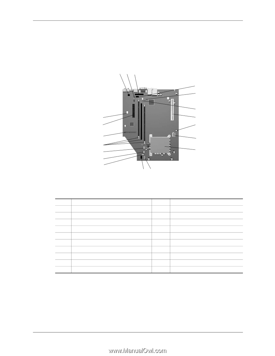
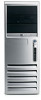
Board Layouts, s 2-16 through 2-18 show the system and expansion boards for these systems.
 |
View all Compaq dc7100 manuals
Add to My Manuals
Save this manual to your list of manuals |
Page 35 highlights
System Overview 2.3.3 Board Layouts Figures 2-16 through 2-18 show the system and expansion boards for these systems. 123 4 5 6 o 7 i 8 u 9 y t - r e wq NOTE: See USDT rear chassis illustrations for externally accessible I/O connectors. Item 1 2 3 4 5 6 7 8 9 10 Description Hood sense header Battery Parallel port option header Serial port A header Password clear jumper header SATA #0 header PCI 2.3 slot Intenal speaker header Power supply (VccP) connector Processor socket Figure 2-16. USDT System Board Item 11 12 13 14 15 16 17 18 19 -- Description Power button, power LED, HD LED header Front panel audio connector Front panel USB port connector Chassis fan, secondary connector Chassis fan, primary connector DIMM sockets (3) MultiBay riser connector Power supply connector Auxiliary audio input connector -- Technical Reference Guide 361834-002 2-19
-
 1
1 -
2
-
3
-
4
-
5
-
6
-
7
-
8
-
9
-
10
-
11
-
12
-
13
-
14
-
15
-
16
-
17
-
18
-
19
-
20
-
21
-
22
-
23
-
24
-
25
-
26
-
27
-
28
-
29
-
 30
30 -
 31
31 -
 32
32 -
 33
33 -
 34
34 -
 35
35 -
 36
36 -
 37
37 -
 38
38 -
 39
39 -
 40
40 -
41
-
42
-
43
-
44
-
45
-
46
-
47
-
48
-
49
-
50
-
51
-
52
-
53
-
54
-
55
-
56
-
57
-
58
-
59
-
60
-
61
-
62
-
63
-
64
-
65
-
66
-
67
-
68
-
69
-
70
-
71
-
72
-
73
-
74
-
75
-
76
-
77
-
78
-
79
-
80
-
81
-
82
-
83
-
84
-
85
-
86
-
87
-
88
-
89
-
90
-
91
-
92
-
93
-
94
-
95
-
96
-
97
-
98
-
99
-
100
-
101
-
102
-
103
-
104
-
105
-
106
-
107
-
108
-
109
-
110
-
111
-
112
-
113
-
114
-
115
-
116
-
117
-
118
-
119
-
120
-
121
-
122
-
123
-
124
-
125
-
126
-
127
-
128
-
129
-
130
-
131
-
132
-
133
-
134
-
135
-
136
-
137
-
138
-
139
-
140
-
141
-
142
-
143
-
144
-
145
-
146
-
147
-
148
-
149
-
150
-
151
-
152
-
153
-
154
-
155
-
156
-
157
-
158
-
159
-
160
-
161
-
162
-
163
-
164
-
165
-
166
-
167
-
168
-
169
-
170
-
171
-
172
-
173
-
174
-
175
-
176
-
177
-
178
-
179
-
180
-
181
-
182
-
183
-
184
-
185
-
186
-
187
-
188
-
189
-
190
-
191
-
192
-
193
-
194
-
195
-
196
-
197
-
198
-
199
-
200
-
201
-
202
-
203
-
204
-
205
-
206
-
207
-
208
-
209
-
210
-
211
-
212
 |
 |