Compaq dc7100 HP Compaq dc71xx and dx61xx Series Business Desktop Computers Te - Page 118
Audio Codec, multiple audio inputs.
 |
View all Compaq dc7100 manuals
Add to My Manuals
Save this manual to your list of manuals |
Page 118 highlights
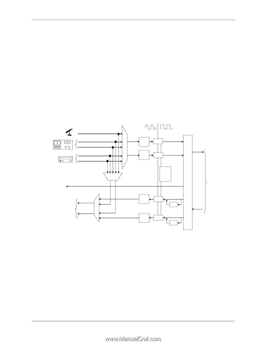
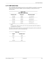
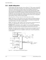
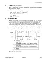
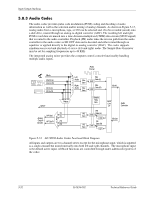
Input/Output Interfaces 5.8.3 Audio Codec The audio codec provides pulse code modulation (PCM) coding and decoding of audio information as well as the selection and/or mixing of analog channels. As shown in Figure 5-13, analog audio from a microphone, tape, or CD can be selected and, if to be recorded (saved) onto a disk drive, routed through an analog-to-digital converter (ADC). The resulting left and right PCM record data are muxed into a time-division-multiplexed (TDM) data stream (SD IN signal) that is routed to the audio controller. Playback (PB) audio takes the reverse path from the audio controller to the audio codec as SD OUT data and is decoded and either routed through an equalizer or applied directly to the digital-to-analog converter (DAC). The codec supports simultaneous record and playback of stereo (left and right) audio. The Sample Rate Generator may be set for sampling frequencies up to 48 KHz. The integrated analog mixer provides the computer control-console functionality handling multiple audio inputs. Audio Format Mic In Line In (L) Line In (R) CD In (L) CD In (R) S e l Left Audio Rec e Gain c Right t Audio Rec o Gain r SPDIF Σ/Mixer (L) PB Analog Output Circuits HP Out L S (L) E HP Out R L (R) (R) Gain PB Gain Rec Data (L) ADC Rec Data (R) ADC Sample Rate Gen. PB Data (L) DAC EQ PB Data (R) DAC EQ SD IN AC97 Link I/F Audio Controller SD Out Figure 5-13. AD1981B Audio Codec Functional Block Diagram All inputs and outputs are two-channel stereo except for the microphone input, which is inputted as a single-channel but mixed internally onto both left and right channels. The microphone input is the default active input. All block functions are controlled through index-addressed registers of the codec. 5-32 361834-002 Technical Reference Guide
-
 1
1 -
2
-
3
-
4
-
5
-
6
-
7
-
8
-
9
-
10
-
11
-
12
-
13
-
14
-
15
-
16
-
17
-
18
-
19
-
20
-
21
-
22
-
23
-
24
-
25
-
26
-
27
-
28
-
29
-
30
-
31
-
32
-
33
-
34
-
35
-
36
-
37
-
38
-
39
-
40
-
41
-
42
-
43
-
44
-
45
-
46
-
47
-
48
-
49
-
50
-
51
-
52
-
53
-
54
-
55
-
56
-
57
-
58
-
59
-
60
-
61
-
62
-
63
-
64
-
65
-
66
-
67
-
68
-
69
-
70
-
71
-
72
-
73
-
74
-
75
-
76
-
77
-
78
-
79
-
80
-
81
-
82
-
83
-
84
-
85
-
86
-
87
-
88
-
89
-
90
-
91
-
92
-
93
-
94
-
95
-
96
-
97
-
98
-
99
-
100
-
101
-
102
-
103
-
104
-
105
-
106
-
107
-
108
-
109
-
110
-
111
-
112
-
 113
113 -
 114
114 -
 115
115 -
 116
116 -
 117
117 -
 118
118 -
 119
119 -
 120
120 -
 121
121 -
 122
122 -
 123
123 -
124
-
125
-
126
-
127
-
128
-
129
-
130
-
131
-
132
-
133
-
134
-
135
-
136
-
137
-
138
-
139
-
140
-
141
-
142
-
143
-
144
-
145
-
146
-
147
-
148
-
149
-
150
-
151
-
152
-
153
-
154
-
155
-
156
-
157
-
158
-
159
-
160
-
161
-
162
-
163
-
164
-
165
-
166
-
167
-
168
-
169
-
170
-
171
-
172
-
173
-
174
-
175
-
176
-
177
-
178
-
179
-
180
-
181
-
182
-
183
-
184
-
185
-
186
-
187
-
188
-
189
-
190
-
191
-
192
-
193
-
194
-
195
-
196
-
197
-
198
-
199
-
200
-
201
-
202
-
203
-
204
-
205
-
206
-
207
-
208
-
209
-
210
-
211
-
212
 |
 |