Compaq dc7100 HP Compaq dc71xx and dx61xx Series Business Desktop Computers Te - Page 61
Configuration Cycles, PCI Configuration Data Register, I/O Port 0CF8h, R/W, 32-bit access only
 |
View all Compaq dc7100 manuals
Add to My Manuals
Save this manual to your list of manuals |
Page 61 highlights
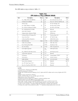
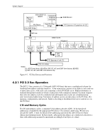
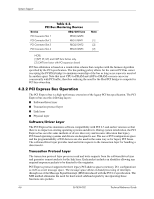
System Support Configuration Cycles Devices on the PCI bus must comply with PCI protocol that allows configuration of that device by software. In this system, configuration mechanism #1 (as described in the PCI Local Bus specification Rev. 2.3) is employed. This method uses two 32-bit registers for initiating a configuration cycle for accessing the configuration space of a PCI device. The configuration address register (CONFIG_ADDRESS) at 0CF8h holds a value that specifies the PCI bus, PCI device, and specific register to be accessed. The configuration data register (CONFIG_DATA) at 0CFCh contains the configuration data. PCI Configuration Data Register PCI Configuration Address Register I/O Port 0CFCh, R/W, (8-, 16-, 32-bit access) I/O Port 0CF8h, R/W, (32-bit access only) Bit 31 30..24 Function Configuration Enable 0 = Disabled 1 = Enable Reserved-read/write 0s Bit 31..0 Function Configuration Data. 23..16 15..11 Bus Number. Selects PCI bus PCI Device Number. Selects PCI device for access 10..8 Function Number. Selects function of selected PCI device. 7..2 Register Index. Specifies config. reg. 1,0 Configuration Cycle Type ID. 00 = Type 0 01 = Type 1 Two types of configuration cycles are used. A Type 0 (zero) cycle is targeted to a device on the PCI bus on which the cycle is running. A Type 1 cycle is targeted to a device on a downstream PCI bus as identified by bus number bits . With three or more PCI buses, a PCI bridge may convert a Type 1 to a Type 0 if it's destined for a device being serviced by that bridge or it may forward the Type 1 cycle unmodified if it is destined for a device being serviced by a downstream bridge. Figure 4-2 shows the configuration cycle format and how the loading of 0CF8h results in a Type 0 configuration cycle on the PCI bus. The Device Number (bits determines which one of the AD31..11 lines is to be asserted high for the IDSEL signal, which acts as a "chip select" function for the PCI device to be configured. The function number (CF8h, bits ) is used to select a particular function within a PCI component. 3 Register 0CF8h Results in: 22 11 11 8 7 2 1 0 [1] Reserved Bus Number Device Number Function Register Number Index AD31..0 (w/Type 00 Config. Cycle) IDSEL (only one signal line asserted) Function Register Number Index NOTES: [1] Bits : 00 = Type 0 Cycle, 01 = Type 1 cycle Type 01 cycle only. Reserved on Type 00 cycle. Figure 4-2. Configuration Cycle Technical Reference Guide 361834-002 4-3
-
 1
1 -
2
-
3
-
4
-
5
-
6
-
7
-
8
-
9
-
10
-
11
-
12
-
13
-
14
-
15
-
16
-
17
-
18
-
19
-
20
-
21
-
22
-
23
-
24
-
25
-
26
-
27
-
28
-
29
-
30
-
31
-
32
-
33
-
34
-
35
-
36
-
37
-
38
-
39
-
40
-
41
-
42
-
43
-
44
-
45
-
46
-
47
-
48
-
49
-
50
-
51
-
52
-
53
-
54
-
55
-
 56
56 -
 57
57 -
 58
58 -
 59
59 -
 60
60 -
 61
61 -
 62
62 -
 63
63 -
 64
64 -
 65
65 -
 66
66 -
67
-
68
-
69
-
70
-
71
-
72
-
73
-
74
-
75
-
76
-
77
-
78
-
79
-
80
-
81
-
82
-
83
-
84
-
85
-
86
-
87
-
88
-
89
-
90
-
91
-
92
-
93
-
94
-
95
-
96
-
97
-
98
-
99
-
100
-
101
-
102
-
103
-
104
-
105
-
106
-
107
-
108
-
109
-
110
-
111
-
112
-
113
-
114
-
115
-
116
-
117
-
118
-
119
-
120
-
121
-
122
-
123
-
124
-
125
-
126
-
127
-
128
-
129
-
130
-
131
-
132
-
133
-
134
-
135
-
136
-
137
-
138
-
139
-
140
-
141
-
142
-
143
-
144
-
145
-
146
-
147
-
148
-
149
-
150
-
151
-
152
-
153
-
154
-
155
-
156
-
157
-
158
-
159
-
160
-
161
-
162
-
163
-
164
-
165
-
166
-
167
-
168
-
169
-
170
-
171
-
172
-
173
-
174
-
175
-
176
-
177
-
178
-
179
-
180
-
181
-
182
-
183
-
184
-
185
-
186
-
187
-
188
-
189
-
190
-
191
-
192
-
193
-
194
-
195
-
196
-
197
-
198
-
199
-
200
-
201
-
202
-
203
-
204
-
205
-
206
-
207
-
208
-
209
-
210
-
211
-
212
 |
 |