Craftsman 79193 Operation Manual - Page 7
NOTE:Whenusing - sears
 |
View all Craftsman 79193 manuals
Add to My Manuals
Save this manual to your list of manuals |
Page 7 highlights
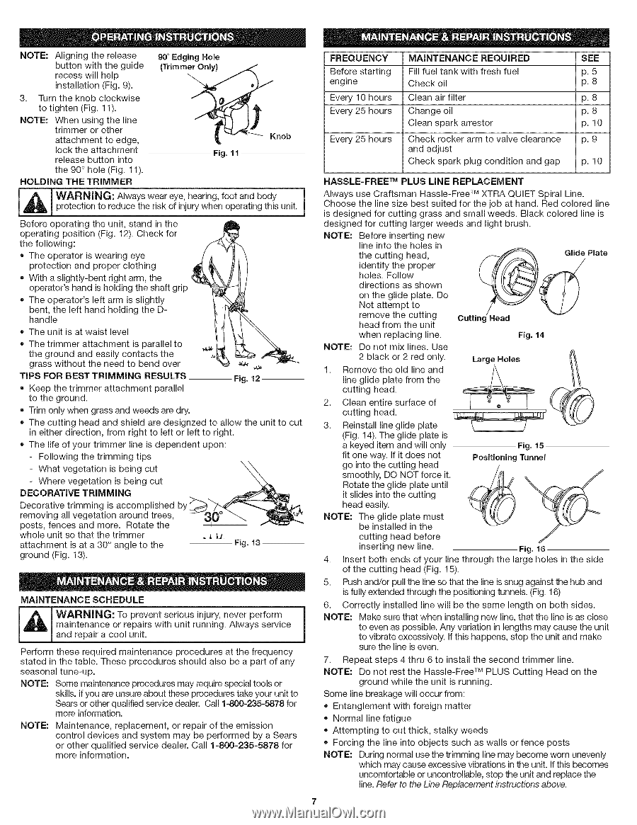
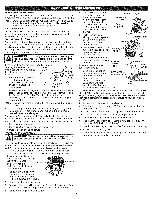
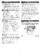
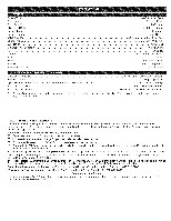
NOTEA: lignintgherelease 90 ° Edging Hole buttonwiththeguide recesws illhelp installatio(Fnig9. ). 3. Turntheknobclockwise totighten(Fig1. 1). NOTE:Whenusingtheline trimmeorrother (Trimm j__-_-._ Knob attachmetnotedge, locktheattachment releasbeuttoninto Fig. 11 the90° hole(Fig1. 1). HOLDING THE TRIMMER m I A I WARNING: Always wear eye, hearing, foot and body protection to reduce the risk of injury when operating this unit. j Before operating the unit, stand in the operating position (Fig. 12). Check for the following: • The operator is wearing eye protection and proper clothing With a slightly-bent right arm, the operator's hand is holding the shaft grip The operator's left arm is slightly bent, the left hand holding the Dhandle The unit is at waist level The trimmer attachment is parallel to the ground and easily contacts the grass without the need to bend over _ ,_ TiPS FOR BEST TRiMMiNG RESULTS • Keep the trimmer attachment parallel to the ground. Fig. 12 Trim only when grass and weeds are dry. The cutting head and shield are designzed to allow the unit to cut in either direction, from right to left or left to right. The life of your trimmer line is dependent upon: - Following the trimming tips - Where vegetation is being cut DECORATIVE TRiMMiNG - What vegetation is being cut _ Decorative trimming is accomplished by removing all vegetation around trees, posts, fences and more. Rotate the whole unit so that the trimmer attachment is at a 30 ° angle to the ground (Fig. 13). 30 _ _ L_ _ _ _ Fig. 13 MAINTENANCE SCHEDULE maintenance or repairs with unit running. Always service _dIL_[lL [ WanAdRNreIpNaGir: a coTo°l upnreitv. ent seri°us injury' never perf°rm 1 Perform these required maintenance procedures at the frequency stated in the table. These procedures should also be a part of any seasonal tune-up. NOTE: Some maintenance procedures may require special tools or skills. Ifyou are unsure about these procedures take your unit to Sears or other qualified service dealer. Call 1=800-235=5878 for more information. NOTE: Maintenance, replacement, or repair of the emission control devices and system may be performed by a Sears or other qualified service dealer. Call 1-800-235-5878 for more information. FREQUENCY Before starting engine Every 10 hours Every 25 hours Every 25 hours MAINTENANCE REQUIRED Fill fuel tank with fresh fuel Check oil Clean air filter Change oil Clean spark arrestor Check rocker arm to valve clearance and adjust Check spark plug condition and gap SEE p. 5 p. 8 p. 8 p. 8 p. 10 p. 9 p. 10 HASSLE-FREE TM PLUS LiNE REPLACEMENT Always use Craftsman Hassle-Free TM XTRA QUIET Spiral Line. Choose the line size best suited for the job at hand. Red colored line is designed for cutting grass and small weeds. Black colored line is designed for cutting larger weeds and light brush. NOTE: Before inserting new line into the holes in the cutting head, identify the proper holes. Follow directions as shown on the glide plate. Do Not attempt to Glide Plate NOTE: remove the cutting head from the unit when replacing line. Do not mix lines. Use Cutting -lead Fig. 14 2 black or 2 red only. Large Holes line glide plate from the cutting head. 2. Clean entire surface of 1. Rcuetmtinogvehethaed.old line and _/\ (_ 3. Reinstall line glide plate (Fig. 14). The glide plate is a keyed item and will only Fig. 15 fit one way. If it does not go into the cutting head smoothly, DO NOT force it. Rotate the glide plate until it slides into the cutting head easily. PositioningTunnel NOTE: The glide plate must be installed in the cutting head before inserting new line. Fig. 16 4. insert both ends of your line through the large holes in the side of the cutting head (Fig. 15). 5. Push and/or pull the line so that the line is snug against the hub and is fully extended through the positioning tunnels. (Fig. 16) 6. Correctly installed line will be the same length on both sides. NOTE: Make sure that when installing new line, that the line is as close to even as possible. Any variation in lengths may cause the unit to vibrate excessively. If this happens, stop the unit and make sure the line is even. 7. Repeat steps 4 thru 6 to install the second trimmer line. NOTE: Do not rest the Hassle-Free TM PLUS Cutting Head on the ground while the unit is running. Some line breakage will occur from: Entanglement with foreign matter Normal line fatigue Attempting to cut thick, stalky weeds Forcing the line into objects such as walls or fence posts NOTE: During normal use the trimming line may become worn unevenly which may cause excessive vibrations in the unit. If this becomes uncomfortable or uncontrollable, stop the unit and replace the line.Refer to the Line Replacement instructions above.
-
 1
1 -
 2
2 -
 3
3 -
 4
4 -
 5
5 -
 6
6 -
 7
7 -
 8
8 -
 9
9 -
 10
10 -
 11
11 -
 12
12 -
13
-
14
-
15
-
16
-
17
-
18
-
19
-
20
-
21
-
22
-
23
-
24
-
25
-
26
-
27
-
28
-
29
-
30
-
31
-
32
 |
 |