D-Link DGS-1100-08V2 User Manual 1.00 WW - Page 11
Hardware Installation, Step 1: Unpacking, Step 2: Switch Installation, Desktop or Shelf Installation
 |
View all D-Link DGS-1100-08V2 manuals
Add to My Manuals
Save this manual to your list of manuals |
Page 11 highlights
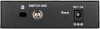
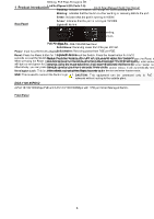
2 Hardware Installation D-Link Smart Managed Switch User Manual 2 Hardware Installation This chapter provides unpacking and installation information for your D-Link DGS-110005V2/05PDV2/08V2/08PV2 Smart Managed Switch. Step 1: Unpacking Open the shipping carton and carefully unpack its contents. Please consult the packing list below to make sure all items are present and undamaged. One DGS-1100-05V2/05PDV2/08V2/08PV2 Smart Managed Switch One AC external power adapter Four rubber feet Wall-mount kit Quick Installation Guide CD (User manual) If any item is found missing or damaged, please contact the local reseller for replacement. Step 2: Switch Installation For safe switch installation and operation, it is recommended to you: Visually inspect the power cord to see that it is secured fully to the AC power connector. Make sure that there is proper heat dissipation and adequate ventilation around the switch. Do not place heavy objects on the switch. Desktop or Shelf Installation The DGS-1100 series switches come with a strip of four adhesive rubber pads that can be placed on the bottom of the device to prevent the device from damaging the desktop or shelf it is places on. To attach the rubber pads, simply remove them from the adhesive strip and stick one pad on each corner on the bottom panel of the Switch. Figure 2.1 - Attach the adhesive rubber pads to the bottom Wall-mount The Switch can be mounted on a wall. Two mounting slots are provided on the bottom of the switch for this purpose. Please refer to the instructions below on how to complete the wall-mounting process. Mounting on a cement wall Step 1: Drill two holes that align with the keyholes on the back of the Switch in the wall where you want to mount the device, and place the two indluded nylon screw anchors into the drilled holes. Step 2: Drive the included screws into the nylon screw anchors. Step 3: Hook the mounting keyholes on the back of the Switch onto the screws to secure the device to the wall. Mounting on a wood wall Step 1: Drive the included screws into a wood wall. 8
-
 1
1 -
2
-
3
-
4
-
5
-
 6
6 -
 7
7 -
 8
8 -
 9
9 -
 10
10 -
 11
11 -
 12
12 -
 13
13 -
 14
14 -
 15
15 -
 16
16 -
17
-
18
-
19
-
20
-
21
-
22
-
23
-
24
-
25
-
26
-
27
-
28
-
29
-
30
-
31
-
32
-
33
-
34
-
35
-
36
-
37
-
38
-
39
-
40
-
41
-
42
-
43
-
44
-
45
-
46
-
47
-
48
-
49
-
50
-
51
-
52
-
53
-
54
-
55
-
56
 |
 |
