D-Link DGS-1100-08V2 User Manual 1.00 WW - Page 12
Metal screw M7 type; Length 16 mm, Number of screws *2 for DGS-1100-05V2/05PDV2/08V2/08PV2
 |
View all D-Link DGS-1100-08V2 manuals
Add to My Manuals
Save this manual to your list of manuals |
Page 12 highlights
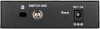
2 Hardware Installation D-Link Smart Managed Switch User Manual Step 2. Hook the mounting keyholes on the back of the Switch onto the screws to secure the device to the wall. Figure 2.2 - Wall mount installation Metal screw (M7 type; Length 16 mm, Number of screws *2) for DGS-1100-05V2/05PDV2/08V2/08PV2 Vis métallique (type M7 ; longueur 16 mm, nombre de vis *2) pour DGS-1100-05V2/05PDV2/08V2/08PV2 9
-
 1
1 -
2
-
3
-
4
-
5
-
6
-
 7
7 -
 8
8 -
 9
9 -
 10
10 -
 11
11 -
 12
12 -
 13
13 -
 14
14 -
 15
15 -
 16
16 -
 17
17 -
18
-
19
-
20
-
21
-
22
-
23
-
24
-
25
-
26
-
27
-
28
-
29
-
30
-
31
-
32
-
33
-
34
-
35
-
36
-
37
-
38
-
39
-
40
-
41
-
42
-
43
-
44
-
45
-
46
-
47
-
48
-
49
-
50
-
51
-
52
-
53
-
54
-
55
-
56
 |
 |

2
Hardware Installation
D-Link Smart Managed Switch User Manual
9
Step 2. Hook the mounting keyholes on the back of the Switch onto the screws to secure the device to
the wall.
Figure 2.2 – Wall mount installation
Metal screw (M7 type; Length 16 mm, Number of screws *2) for DGS-1100-05V2/05PDV2/08V2/08PV2
Vis métallique (type M7 ; longueur 16 mm, nombre de vis *2) pour DGS-1100-05V2/05PDV2/08V2/08PV2