D-Link DSS-200G-28MPP Product Manual - Page 27
Connecting the Alarm Cable, Switch Model, Port Numbers, Power Rating
 |
View all D-Link DSS-200G-28MPP manuals
Add to My Manuals
Save this manual to your list of manuals |
Page 27 highlights
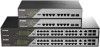
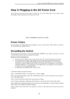
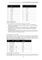
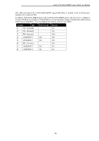
D-Link DSS-200G MP/MPP series Switch User Manual Figure 3-5 Ground cable, screw and #8 terminal lug rings CAUTION: This equipment is to be connected only to PoE networks without routing to the outside plant. Connecting the Alarm Cable The system can send out alarms through system logs and traps and it can also trigger an alarm device such as a siren. The alarm port activates alarms when the front Alert LED flashes due to PoE malfunctioning events. The alarm port has an RJ45 connector; however, its pinout is not the same as the common RJ45 connector for connecting a network cable. Only the first 2 pins (of the 8 pins) can be used to connect to the alarm device. Connecting the PoE Cable The DSS-200G MP/MPP Series switches support the IEEE 802.3af and 802.3at Power over Ethernet (PoE) standards. The DSS-200G MPP Series also support the IEEE 802.3bt standard. The ports and power ratings per switch are as follows: Switch Model Port Numbers Power Rating DSS-200G-10MP 1 - 8 30 W DSS-200G-10MPP 1 - 8 90 W DSS-200G-28MP 1 - 24 30 W DSS-200G-28MPP 1 - 8 9 - 24 90 W 30 W Power can be supplied at 48VDC to Powered Devices (PDs) over Category 5 or Category 6 UTP Ethernet cables. The switches follow the standard PSE (Power Sourcing Equipment) pinout Alternative B. The DSS-200G MP/MPP Series switches include the following PoE features: • Auto-discovery recognizes the connection of a PD (Powered Device) and automatically sends power to it. • The Auto-disable feature occurs under two conditions: firstly, if the total power consumption exceeds the system power limit; and secondly, if the per port power consumption exceeds the per port power limit. • Active circuit protection automatically disables the port if there is a short. Other ports will remain active. Based on 802.3af/at/bt PDs receive power according to the following classification: PSE provides power according to the following classification: 22
-
 1
1 -
2
-
3
-
4
-
5
-
6
-
7
-
8
-
9
-
10
-
11
-
12
-
13
-
14
-
15
-
16
-
17
-
18
-
19
-
20
-
21
-
 22
22 -
 23
23 -
 24
24 -
 25
25 -
 26
26 -
 27
27 -
 28
28 -
 29
29 -
 30
30 -
 31
31 -
 32
32 -
33
-
34
-
35
-
36
-
37
-
38
-
39
-
40
-
41
-
42
-
43
-
44
-
45
-
46
-
47
-
48
-
49
-
50
-
51
-
52
-
53
-
54
-
55
-
56
-
57
-
58
-
59
-
60
-
61
-
62
-
63
-
64
-
65
-
66
-
67
-
68
-
69
-
70
-
71
-
72
-
73
-
74
-
75
-
76
-
77
-
78
-
79
-
80
-
81
-
82
-
83
-
84
-
85
-
86
-
87
-
88
-
89
-
90
-
91
-
92
-
93
-
94
-
95
-
96
-
97
-
98
-
99
-
100
-
101
-
102
-
103
-
104
-
105
-
106
-
107
-
108
-
109
-
110
-
111
-
112
-
113
-
114
-
115
-
116
-
117
-
118
-
119
-
120
-
121
-
122
-
123
-
124
-
125
-
126
-
127
-
128
-
129
-
130
-
131
-
132
-
133
-
134
-
135
-
136
 |
 |