Dell AX4-5 Hardware Installation Guide - Page 18
in each node are connected to each other for the private network and
 |
View all Dell AX4-5 manuals
Add to My Manuals
Save this manual to your list of manuals |
Page 18 highlights
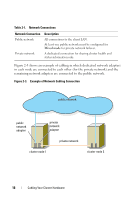
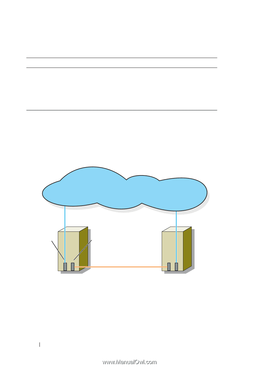
Table 2-1. Network Connections Network Connection Public network Private network Description All connections to the client LAN. At least one public network must be configured for Mixed mode for private network failover. A dedicated connection for sharing cluster health and status information only. Figure 2-3 shows an example of cabling in which dedicated network adapters in each node are connected to each other (for the private network) and the remaining network adapters are connected to the public network. Figure 2-3. Example of Network Cabling Connection public network public network adapter private network adapter private network cluster node 1 cluster node 2 18 Cabling Your Cluster Hardware
-
 1
1 -
2
-
3
-
4
-
5
-
6
-
7
-
8
-
9
-
10
-
11
-
12
-
 13
13 -
 14
14 -
 15
15 -
 16
16 -
 17
17 -
 18
18 -
 19
19 -
 20
20 -
 21
21 -
 22
22 -
 23
23 -
24
-
25
-
26
-
27
-
28
-
29
-
30
-
31
-
32
-
33
-
34
-
35
-
36
-
37
-
38
-
39
-
40
-
41
-
42
-
43
-
44
-
45
-
46
-
47
-
48
-
49
-
50
-
51
-
52
-
53
-
54
-
55
-
56
-
57
-
58
-
59
-
60
 |
 |
18
Cabling Your Cluster Hardware
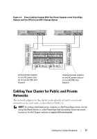
Figure 2-3 shows an example of cabling in which dedicated network adapters
in each node are connected to each other (for the private network) and the
remaining network adapters are connected to the public network.
Figure 2-3.
Example of Network Cabling Connection
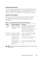
Table 2-1.
Network Connections
Network Connection
Description
Public network
All connections to the client LAN.
At least one public network must be configured for
Mixed mode
for private network failover.
Private network
A dedicated connection for sharing cluster health and
status information only.
cluster node 1
cluster node 2
public network
private network
private
network
adapter
public
network
adapter