Dell Alienware 15 R3 Service Manual - Page 70
latch to secure the cable., Adhere the tape that secures the display cable to the system board.
 |
View all Dell Alienware 15 R3 manuals
Add to My Manuals
Save this manual to your list of manuals |
Page 70 highlights
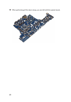
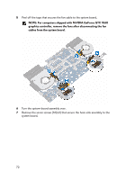
10 Route the coin-cell battery through the routing channel and adhere the tape to secure the cable. 11 Connect the coin-cell battery cable to the system board. 12 Turn the computer over. 13 Connect the logo board cable to the system board. 14 Slide the power-button board cable into its slot on the system board and close the latch to secure the cable. 15 Slide the display cable into the connector on the system board and close the latch to secure the cable. 16 Adhere the tape that secures the display cable to the system board. Post-requisites 1 Replace the memory modules. 2 Replace the battery. 3 Replace the computer base. 4 Replace the rear-I/O cover. 5 Replace the solid-state drive. 6 Follow the procedure from step 4 to step 6 in "Replacing the hard drive". 7 Replace the wireless card. 8 Replace the base cover. 70
-
 1
1 -
2
-
3
-
4
-
5
-
6
-
7
-
8
-
9
-
10
-
11
-
12
-
13
-
14
-
15
-
16
-
17
-
18
-
19
-
20
-
21
-
22
-
23
-
24
-
25
-
26
-
27
-
28
-
29
-
30
-
31
-
32
-
33
-
34
-
35
-
36
-
37
-
38
-
39
-
40
-
41
-
42
-
43
-
44
-
45
-
46
-
47
-
48
-
49
-
50
-
51
-
52
-
53
-
54
-
55
-
56
-
57
-
58
-
59
-
60
-
61
-
62
-
63
-
64
-
 65
65 -
 66
66 -
 67
67 -
 68
68 -
 69
69 -
 70
70 -
 71
71 -
 72
72 -
 73
73 -
 74
74 -
 75
75 -
76
-
77
-
78
-
79
-
80
-
81
-
82
-
83
-
84
-
85
-
86
-
87
-
88
-
89
-
90
-
91
-
92
-
93
-
94
-
95
-
96
-
97
-
98
-
99
-
100
-
101
-
102
-
103
-
104
-
105
-
106
-
107
-
108
-
109
-
110
-
111
-
112
-
113
-
114
-
115
-
116
-
117
-
118
-
119
-
120
-
121
 |
 |