Dell Alienware 15 R3 Service Manual - Page 74
Replacing the heat-sink assembly, Procedure, Post-requisites
 |
View all Dell Alienware 15 R3 manuals
Add to My Manuals
Save this manual to your list of manuals |
Page 74 highlights
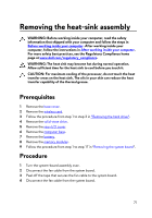
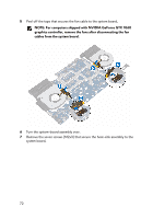
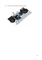
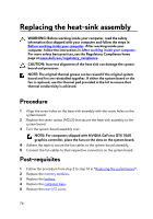
Replacing the heat-sink assembly WARNING: Before working inside your computer, read the safety information that shipped with your computer and follow the steps in Before working inside your computer. After working inside your computer, follow the instructions in After working inside your computer. For more safety best practices, see the Regulatory Compliance home page at www.dell.com/regulatory_compliance. CAUTION: Incorrect alignment of the heat sink can damage the system board and processor. NOTE: The original thermal grease can be reused if the original system board and fan are reinstalled together. If either the system board or the fan is replaced, use the thermal pad provided in the kit to ensure that thermal conductivity is achieved. Procedure 1 Align the screw holes on the heat-sink assembly with the screw holes on the system board. 2 Replace the seven screws (M2x3) that secure the heat-sink assembly to the system board. 3 Turn the system-board assembly over. NOTE: For computers shipped with NVIDIA GeForce GTX 1060 graphics controller, place the fans on the slots on the system board. 4 Adhere the tape to secure the fan cables to the system-board assembly. 5 Connect the fan cables to their respective connectors on the system board. Post-requisites 1 Follow the procedure from step 2 to step 16 in "Replacing the system board". 2 Replace the memory modules. 3 Replace the battery. 4 Replace the computer base. 5 Replace the rear-I/O cover. 74
-
 1
1 -
2
-
3
-
4
-
5
-
6
-
7
-
8
-
9
-
10
-
11
-
12
-
13
-
14
-
15
-
16
-
17
-
18
-
19
-
20
-
21
-
22
-
23
-
24
-
25
-
26
-
27
-
28
-
29
-
30
-
31
-
32
-
33
-
34
-
35
-
36
-
37
-
38
-
39
-
40
-
41
-
42
-
43
-
44
-
45
-
46
-
47
-
48
-
49
-
50
-
51
-
52
-
53
-
54
-
55
-
56
-
57
-
58
-
59
-
60
-
61
-
62
-
63
-
64
-
65
-
66
-
67
-
68
-
 69
69 -
 70
70 -
 71
71 -
 72
72 -
 73
73 -
 74
74 -
 75
75 -
 76
76 -
 77
77 -
 78
78 -
 79
79 -
80
-
81
-
82
-
83
-
84
-
85
-
86
-
87
-
88
-
89
-
90
-
91
-
92
-
93
-
94
-
95
-
96
-
97
-
98
-
99
-
100
-
101
-
102
-
103
-
104
-
105
-
106
-
107
-
108
-
109
-
110
-
111
-
112
-
113
-
114
-
115
-
116
-
117
-
118
-
119
-
120
-
121
 |
 |