Dell Alienware M17x Service Manual - Page 28
Removing the Memory Module(s
 |
UPC - 074450000071
View all Dell Alienware M17x manuals
Add to My Manuals
Save this manual to your list of manuals |
Page 28 highlights
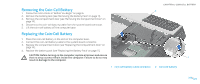
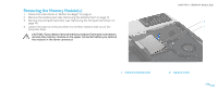
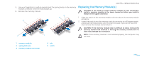
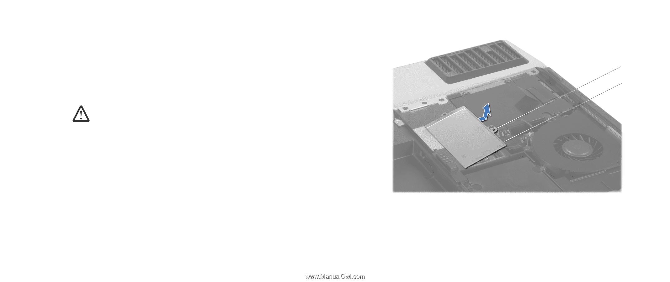
Removing the Memory Module(s) 1. Follow the instructions in "Before You Begin" on page 6. 2. Remove the battery pack (see "Removing the Battery Pack" on page 11). 3. Remove the compartment door (see "Removing the Compartment Door" on page 14). 4. Loosen the captive screw and slide the memory module door out of the computer base. CAUTION: If you need to remove memory modules from both connectors, remove the memory module in the upper connector before you remove the module in the lower connector. CHAPTER 7: MEMORY MODULE(S) 2 1 1 memory module door 2 captive screw 028 /028
-
 1
1 -
2
-
3
-
4
-
5
-
6
-
7
-
8
-
9
-
10
-
11
-
12
-
13
-
14
-
15
-
16
-
17
-
18
-
19
-
20
-
21
-
22
-
 23
23 -
 24
24 -
 25
25 -
 26
26 -
 27
27 -
 28
28 -
 29
29 -
 30
30 -
 31
31 -
 32
32 -
 33
33 -
34
-
35
-
36
-
37
-
38
-
39
-
40
-
41
-
42
-
43
-
44
-
45
-
46
-
47
-
48
-
49
-
50
-
51
-
52
-
53
-
54
-
55
-
56
-
57
-
58
-
59
-
60
-
61
-
62
-
63
-
64
-
65
-
66
-
67
-
68
-
69
-
70
-
71
-
72
-
73
-
74
-
75
-
76
-
77
-
78
-
79
-
80
-
81
-
82
-
83
-
84
-
85
-
86
-
87
-
88
-
89
-
90
-
91
-
92
-
93
-
94
-
95
-
96
-
97
-
98
-
99
-
100
-
101
-
102
-
103
-
104
 |
 |
028
028
/
CHAPTER 7: MEMORY MODULE(S)
Removing the Memory Module(s)
Follow the instructions in “Before You Begin” on page
1.
6
.
Remove the battery pack (see “Removing the Battery Pack” on page
2.
11
).
Remove the compartment door (see “Removing the Compartment Door” on
3.
page
14
).
Loosen the captive screw and slide the memory module door out of the
4.
computer base.
CAUTION: If you need to remove memory modules from both connectors,
remove the memory module in the upper connector before you remove
the module in the lower connector.
1
2
1
memory module door
2
captive screw