Dell Alienware M17x Service Manual - Page 92
Replacing the System Board
 |
UPC - 074450000071
View all Dell Alienware M17x manuals
Add to My Manuals
Save this manual to your list of manuals |
Page 92 highlights
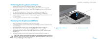
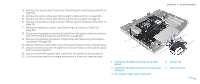
Replacing the System Board 1. Insert the system board at an angle into the computer base. 2. Connect the consumer IR cable to the connectors on the system board and the consumer IR board. 3. Connect the left speaker light cable to the system board connector. 4. Replace the five screws that secure the system board to the computer base. 5. Replace the graphics card blank, if applicable (see "Replacing the Graphics Card Blank" on page 88). 6. Connect the graphics card fan(s) cable to the system board connector (see "Replacing the Graphics Card Fan(s)" on page 85). 7. Replace the graphics card(s) (see "Replacing the Graphics Card(s)" on page 81). 8. Replace the processor heat sink (see "Replacing the Processor Heat Sink" on page 77). 9. Replace the Mini-Card(s) (see "Replacing the Mini-Card(s)" on page 73). 10. Replace the optical drive (see "Replacing the Optical Drive" on page 68). 11. Replace the input/output board (see "Replacing the Input/Output Board" on page 64). 12. Replace the magnesium cover (see "Replacing the Magnesium Cover" on page 51). 13. Replace the left and right brackets (see "Replacing the Brackets" on page 47). 14. Replace the keyboard (see "Replacing the Keyboard" on page 39). 15. Replace the center control cover (see "Replacing the Center Control Cover" on page 35). CHAPTER 21: SYSTEM BOARD 16. Replace the palm rest (see "Replacing the Palm Rest" on page 44). 17. Replace the memory module(s) (see "Replacing the Memory Module(s)" on page 29). 18. Connect the coin-cell battery cable to the system board connector (see "Replacing the Coin-Cell Battery" on page 25). 19. Connect the processor thermal fan cable to the system board connector (see "Replacing the Processor Thermal Fan" on page 22). 20. Replace the hard drive(s) (see "Replacing the Hard Drive(s)" on page 19). 21. Replace the compartment door (see "Replacing the Compartment Door" on page 14). 22. Replace the battery pack (see "Replacing the Battery Pack" on page 11). CAUTION: Before turning on the computer, replace all screws and ensure that no stray screws remain inside the computer. Failure to do so may result in damage to the computer. 23. Turn on the computer. NOTE: After you have replaced the system board, enter the computer Service Tag into the BIOS of the replacement system board. 24. Insert the BIOS upgrade CD that accompanied the replacement system board into the appropriate drive. Follow the instructions that appear on the screen. 092 /092
-
 1
1 -
2
-
3
-
4
-
5
-
6
-
7
-
8
-
9
-
10
-
11
-
12
-
13
-
14
-
15
-
16
-
17
-
18
-
19
-
20
-
21
-
22
-
23
-
24
-
25
-
26
-
27
-
28
-
29
-
30
-
31
-
32
-
33
-
34
-
35
-
36
-
37
-
38
-
39
-
40
-
41
-
42
-
43
-
44
-
45
-
46
-
47
-
48
-
49
-
50
-
51
-
52
-
53
-
54
-
55
-
56
-
57
-
58
-
59
-
60
-
61
-
62
-
63
-
64
-
65
-
66
-
67
-
68
-
69
-
70
-
71
-
72
-
73
-
74
-
75
-
76
-
77
-
78
-
79
-
80
-
81
-
82
-
83
-
84
-
85
-
86
-
 87
87 -
 88
88 -
 89
89 -
 90
90 -
 91
91 -
 92
92 -
 93
93 -
 94
94 -
 95
95 -
 96
96 -
 97
97 -
98
-
99
-
100
-
101
-
102
-
103
-
104
 |
 |