Dell Alienware M17x Service Manual - Page 64
Replacing the Input/Output Board - keyboard light not on
 |
UPC - 074450000071
View all Dell Alienware M17x manuals
Add to My Manuals
Save this manual to your list of manuals |
Page 64 highlights
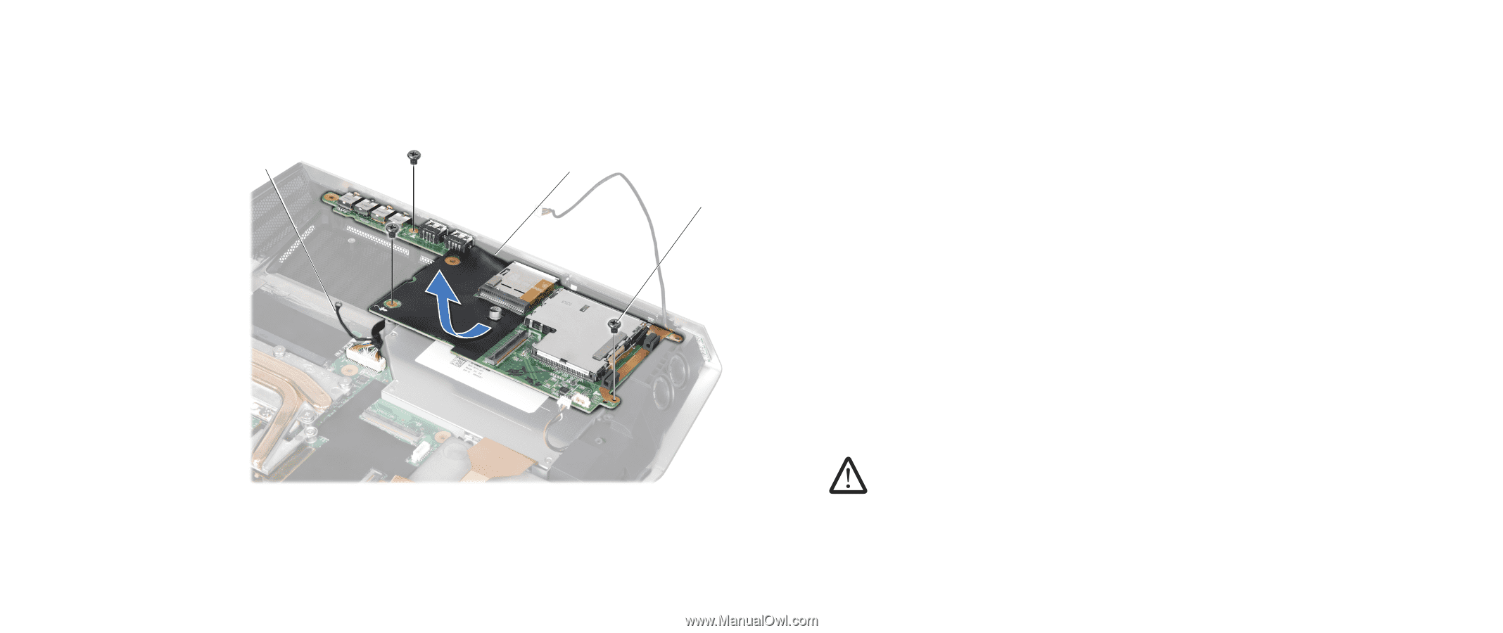
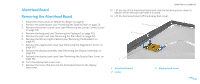
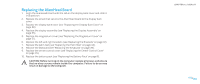
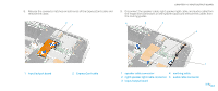
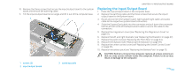
10. Remove the three screws that secure the input/output board to the system board and remove the earthing cable. 11. Tilt the input/output board at an angle and lift it out of the computer base. 3 2 1 CHAPTER 14: INPUT/OUTPUT BOARD Replacing the Input/Output Board 1. Place the input/output board in the computer base. 2. Replace the earthing cable and the three screws that secure the input/ output board to the system board. 3. Route and connect the speaker cable, right speaker light cable, and audio cable to the respective system board connectors. 4. Slide the ExpressCard cable into the connector and pull down the connector latches at both ends of the ExpressCard cable to secure the cable to the connectors. 5. Replace the magnesium cover (see "Replacing the Magnesium Cover" on page 51). 6. Replace the left and right brackets (see "Replacing the Brackets" on page 47). 7. Replace the palm rest (see "Replacing the Palm Rest" on page 44). 8. Replace the keyboard (see "Replacing the Keyboard" on page 39). 9. Replace the center control cover (see "Replacing the Center Control Cover" on page 35). 10. Replace the battery pack (see "Replacing the Battery Pack" on page 11). CAUTION: Before turning on the computer, replace all screws and ensure that no stray screws remain inside the computer. Failure to do so may result in damage to the computer. 1 screws (3) 2 input/output board 3 earthing cable 064 /064
-
 1
1 -
2
-
3
-
4
-
5
-
6
-
7
-
8
-
9
-
10
-
11
-
12
-
13
-
14
-
15
-
16
-
17
-
18
-
19
-
20
-
21
-
22
-
23
-
24
-
25
-
26
-
27
-
28
-
29
-
30
-
31
-
32
-
33
-
34
-
35
-
36
-
37
-
38
-
39
-
40
-
41
-
42
-
43
-
44
-
45
-
46
-
47
-
48
-
49
-
50
-
51
-
52
-
53
-
54
-
55
-
56
-
57
-
58
-
 59
59 -
 60
60 -
 61
61 -
 62
62 -
 63
63 -
 64
64 -
 65
65 -
 66
66 -
 67
67 -
 68
68 -
 69
69 -
70
-
71
-
72
-
73
-
74
-
75
-
76
-
77
-
78
-
79
-
80
-
81
-
82
-
83
-
84
-
85
-
86
-
87
-
88
-
89
-
90
-
91
-
92
-
93
-
94
-
95
-
96
-
97
-
98
-
99
-
100
-
101
-
102
-
103
-
104
 |
 |